Energy-saving and environment-friendly waste heat recycling device
A waste heat recovery, energy saving and environmental protection technology, applied in the direction of heat exchangers, heat transfer modification, heat exchange equipment, etc., can solve the problems of poor waste heat recovery effect, to increase the residence time, increase the diversion effect, increase the collision buffer effect Effect
- Summary
- Abstract
- Description
- Claims
- Application Information
AI Technical Summary
Problems solved by technology
Method used
Image
Examples
Embodiment 1
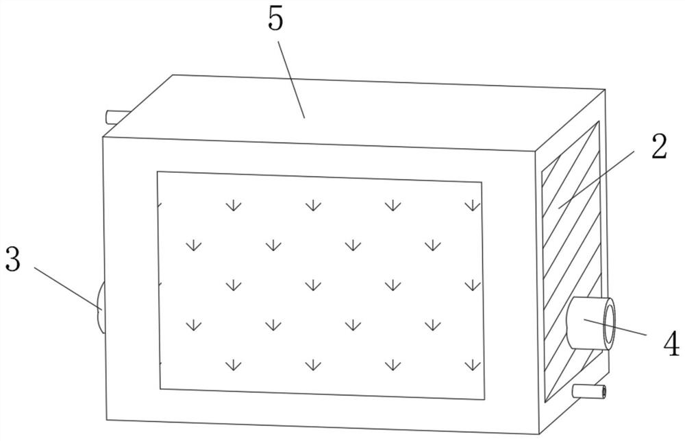
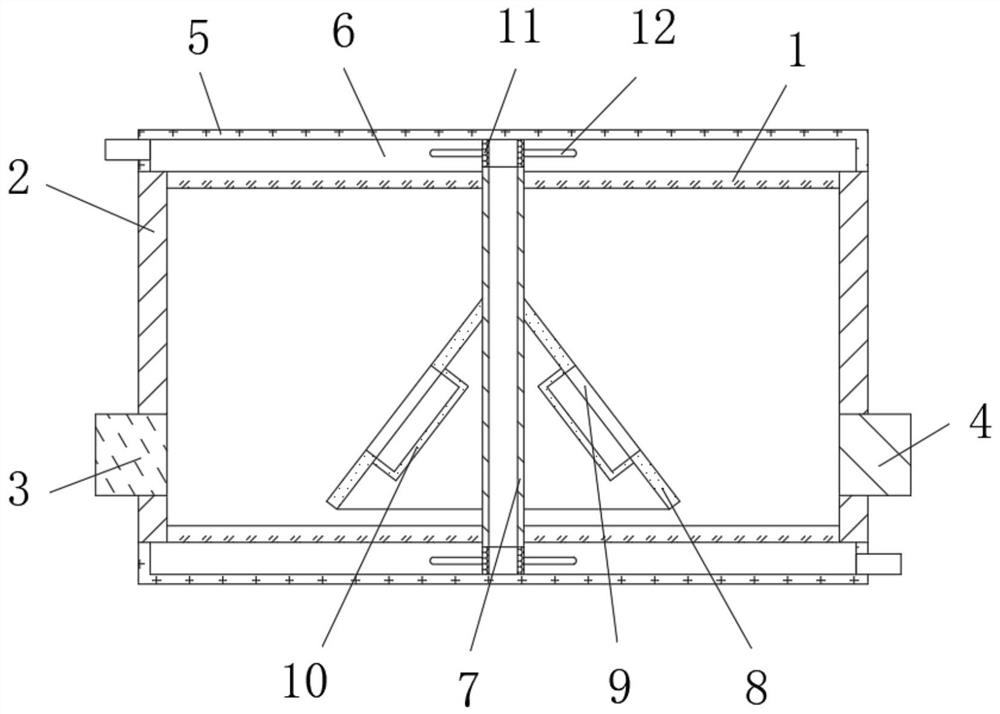
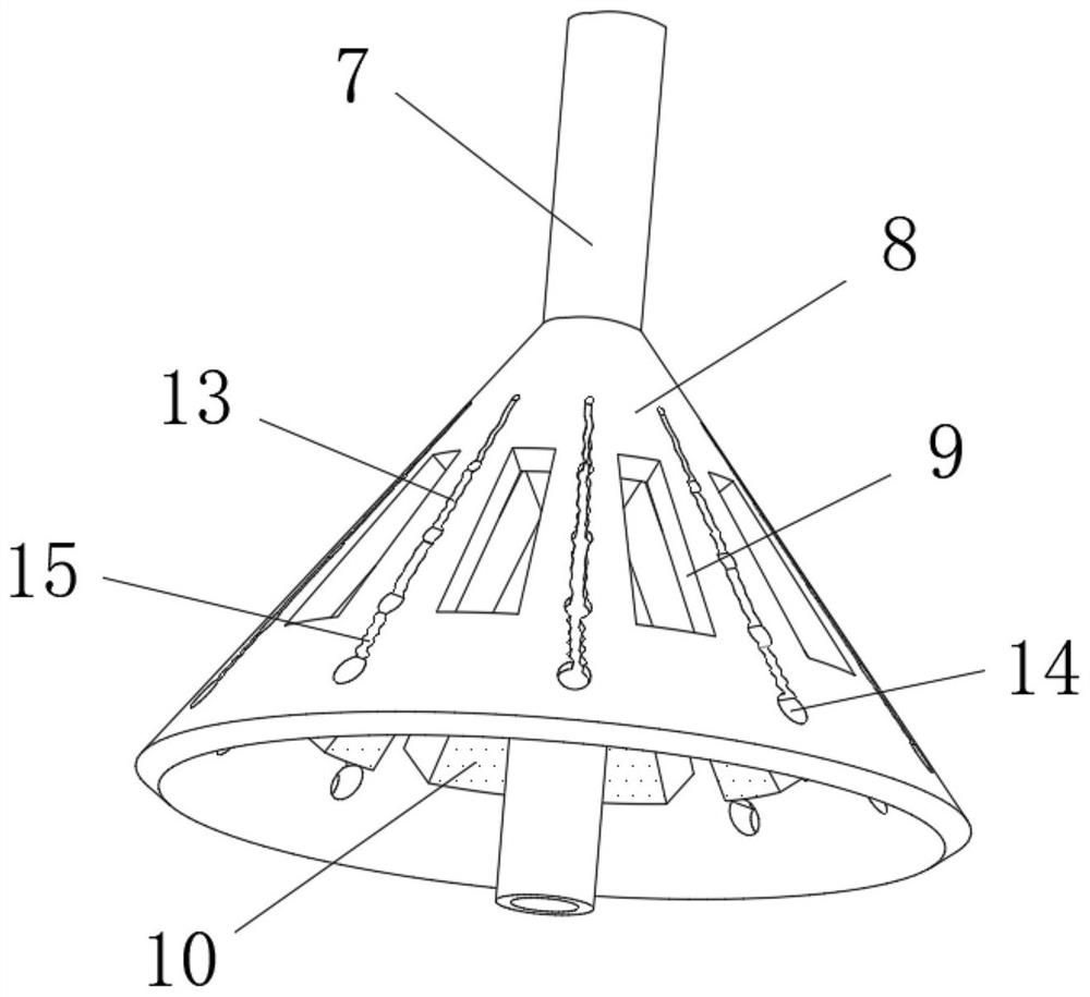
[0027] refer to Figure 1-3 , an energy-saving and environment-friendly waste heat recovery and reuse device, comprising a treatment box 1, the two sides of the treatment box 1 are open, and both sides of the treatment box 1 are fixed with cover plates 2, and the two sides of the treatment box 1 are respectively fixed with air intake pipes 3 and the air outlet pipe 4, the outer wall of the processing cylinder 1 is fixed with a wrapping box 5, and a flow chamber 6 with a "return" structure is formed between the inner wall of the wrapping box 5 and the outer wall of the processing box 1, and the top and bottom of the processing box 1 There is a connecting pipe 7 that runs through it, and the top and bottom ends of the connecting pipe 7 communicate with the flow chamber 6. The outer wall of the connecting pipe 7 is fixed with a flow guide 8 with a ring structure, and the flow guide 8 extends downwards, the cross section of the flow guide 8 is set to a conical structure, and the o...
Embodiment 2
[0032] refer to Figure 1-5 , an energy-saving and environment-friendly waste heat recovery and reuse device, the outer wall of one side of the collision member 12 is provided with a fixed groove 16 penetratingly arranged, and the end of the fixed groove 16 away from the connecting net cylinder 11 is arranged in an outwardly arched arc structure The collision plate 17 equidistantly distributed is fixed between the top and the bottom inner wall of the fixed groove 16, and the collision plate 17 is placed obliquely. The outer walls of both sides of the collision plate 17 are provided with auxiliary grooves 18 equidistantly distributed, and the auxiliary groove 18 The cross-section of the collision plate 17 is configured as a V-shaped structure, and the auxiliary grooves 18 on both sides of the collision plate 17 are arranged at intervals.
[0033] When in use, the inclined collision plate 17 and the auxiliary grooves 18 spaced apart on the side of the collision plate 17 are used...
PUM
 Abstract
Description
Claims
Application Information
 - R&D
- Intellectual Property
- Life Sciences
- Materials
- Tech Scout
- Unparalleled Data Quality
- Higher Quality Content
- 60% Fewer Hallucinations
Browse by: Latest US Patents, China's latest patents, Technical Efficacy Thesaurus, Application Domain, Technology Topic, Popular Technical Reports.
© 2025 PatSnap. All rights reserved.Legal|Privacy policy|Modern Slavery Act Transparency Statement|Sitemap|About US| Contact US: help@patsnap.com


