Eureka AIR delivers breakthrough ideas for toughest innovation challenges, trusted by R&D personnel around the world.

Corrosion process of anode foil for high-voltage aluminum electrolytic capacitor

A technology of aluminum electrolytic capacitors and anode foils, applied in electrolytic capacitors, capacitors, circuits, etc., can solve the problems of low capacity, low production line efficiency, poor hole consistency, etc., achieve high production efficiency, reduce environmental protection investment, and solve the problem of discoloration Effect

Active Publication Date: 2020-12-04
乌鲁木齐众荣电子材料科技有限公司
View PDF7 Cites 1 Cited by
  • Summary
  • Abstract
  • Description
  • Claims
  • Application Information

AI Technical Summary

Problems solved by technology

However, in this scheme, the first electrolysis adopts first-level electrochemical corrosion, and the uniformity of the pores is poor, and the second electrolysis adopts chemical corrosion, but the capacity is low and the production line efficiency is low

Method used

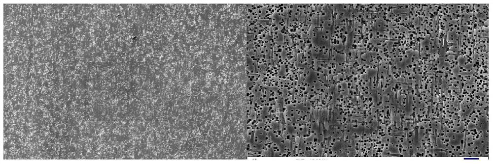
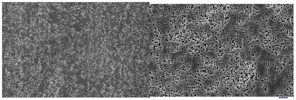
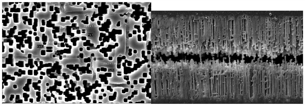

Image

  • Corrosion process of anode foil for high-voltage aluminum electrolytic capacitor
  • Corrosion process of anode foil for high-voltage aluminum electrolytic capacitor
  • Corrosion process of anode foil for high-voltage aluminum electrolytic capacitor

Examples


Embodiment 1

[0043] The specific operation steps are as follows:

[0044] (1) Pretreatment: place the annealed electronic aluminum foil with a purity of 99.99% in a fluorine-containing acid solution with a concentration of 1 wt%, and treat it at 50°C for 2 minutes;

[0045] (2) Electrolysis for the first time porosity: The aluminum foil that has been pretreated and cleaned is subjected to the first stage of electrification treatment in a solution containing 30wt% sulfuric acid, 6wt% hydrochloric acid, and 0.4wt% aluminum ions at a temperature of 70°C and a current density of 0.25A / cm 2 , corroded for 25s;

[0046] (3) Electrolysis for the second porosity: the aluminum foil that has undergone the first porosity is subjected to a first-stage electrification treatment in a solution containing 30wt% sulfuric acid, 6wt% hydrochloric acid, and 0.6wt% aluminum ions at a temperature of 70°C and a current density of 0.25A / cm 2 , corroded for 25s;

[0047] (4) The third hole of electrolysis: the...

Embodiment 2

[0055] The specific operation steps are as follows:

[0056] (1) Pretreatment: place the annealed electronic aluminum foil with a purity of 99.99% in a fluorine-containing acid solution with a concentration of 1.0 wt%, and treat it at 45°C for 1.0 min;

[0057] (2) Electrolysis for the first time porosity: the pre-treated and cleaned aluminum foil is subjected to a first-stage electrification treatment in a solution containing 30wt% sulfuric acid, 3wt% hydrochloric acid, and 0.4wt% aluminum ions at a temperature of 69°C and a current density of 0.20 / cm 2 , corroded for 30s;

[0058] (3) Electrolysis for the second hole: the aluminum foil that has passed through the first hole is subjected to the first stage of electrification treatment in a solution containing 30wt% sulfuric acid, 3wt% hydrochloric acid, and 0.6wt% aluminum ions. The temperature is 69 ° C, and the current density 0.20A / cm 2 , corroded for 30s;

[0059] (4) The third hole of electrolysis: the aluminum foil ...


PUM


Abstract

The invention relates to a corrosion process of an anode foil for a high-voltage aluminum electrolytic capacitor. The invention discloses a corrosion process of an anode foil for a high-voltage aluminum electrolytic capacitor. The corrosion process comprises the following steps: sequentially carrying out pre-treatment, cleaning, electrolytic five-time hole forming, chemical hole expansion and post-treatment on an aluminum foil which is subjected to annealing treatment and has the purity of 99.99%. According to the invention, the corrosion process of the anode foil for the high-voltage aluminumelectrolytic capacitor is a high-efficiency, low-cost and phosphorus-nitrogen-free corrosion production process, can be applied to production of the corrosion process of the anode foil for the aluminum electrolytic capacitor, is high in production efficiency, high in capacity and low in cost, and can meet the requirements of existing customers.

Description

technical field [0001] The invention belongs to the technical field of anode foils for electrolytic capacitors, in particular to a corrosion process for anode foils for high-voltage aluminum electrolytic capacitors. Background technique [0002] Aluminum electrolytic capacitors have been widely used in electronic products due to their simple preparation, low price and superior performance. With the rapid development of the electronic industry, the scale and market demand continue to grow. At present, electrochemical corrosion is mostly used in the corrosion process of anode foil of aluminum electrolytic capacitors, including four steps of pretreatment, primary hole formation, secondary hole expansion, and posttreatment. Electrochemical corrosion on the surface of the aluminum foil can enhance the microscopic tunnel holes of the aluminum foil, avoiding the tunnel holes being blocked by the oxide film during the subsequent formation, thereby obtaining a high specific volume. ...

Claims


Application Information

Patent Timeline
Patent Type & Authority Applications(China)
IPC IPC(8): H01G9/055
CPCH01G9/055
Inventor 李新芳杨辉陈嘉庚罗湘平赵刚刚
Owner 乌鲁木齐众荣电子材料科技有限公司
Why Eureka
Eureka Blog
Learn More