
Filtering device for nitrile rubber material manufacturing

A technology of nitrile rubber and filter device, which is applied in the direction of filter screen, solid separation, grid, etc., can solve the problems of poor insulation performance, small amplitude, poor low temperature resistance, etc., and achieve the adjustment of feeding angle, convenient feeding angle, The effect of avoiding the spread of dust

Inactive Publication Date: 2020-12-04
湖南洋韬材料科技有限公司
View PDF9 Cites 0 Cited by
  • Summary
  • Abstract
  • Description
  • Claims
  • Application Information

AI Technical Summary

Problems solved by technology

Its disadvantages are poor low temperature resistance, poor ozone resistance, poor insulation performance, and slightly lower elasticity.
[0003] After the nitrile rubber powder is manufactured, it needs to be filtered to filter the larger nitrile rubber powder. At present, the existing nitrile rubber material is used to make the filter device. When filtering, the vibration motor is usually used to drive the filter. Net filtration, this kind of vibration method has small amplitude and insufficient filtration. Therefore, it is urgent to design a filter device made of nitrile rubber material to solve the above problems

Method used


Image

  • Filtering device for nitrile rubber material manufacturing
  • Filtering device for nitrile rubber material manufacturing
  • Filtering device for nitrile rubber material manufacturing

Examples


Embodiment 1

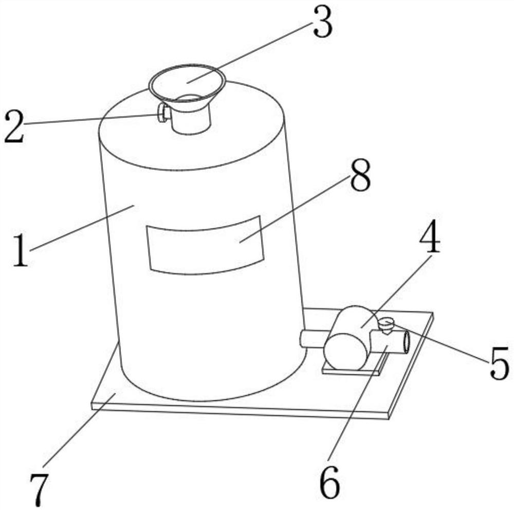
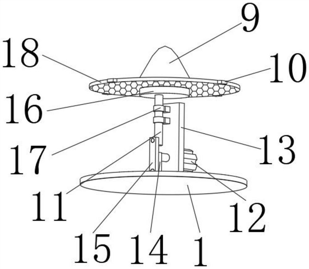
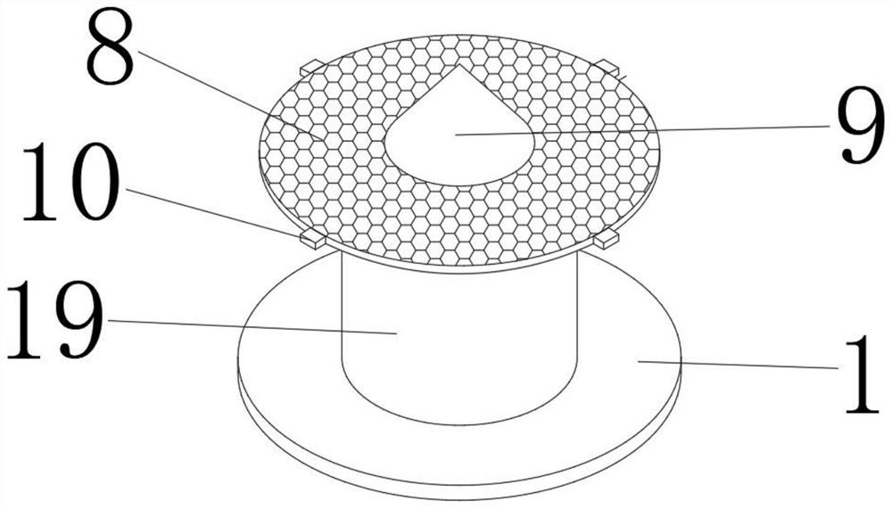
[0025] refer to Figure 1-3 , a nitrile rubber material manufacturing filter device, comprising a filter barrel 1, the bottom inner wall of the filter barrel 1 is connected with a mounting plate 13 by bolts, and one side outer wall of the mounting plate 13 is connected with a rotating motor 12 by bolts, and the rotating motor 12 The output shaft is connected with a rotating rod 14 through bolts, and one end of the rotating rod 14 is connected with a connecting rod 15 through a rotating shaft, one end of the connecting rod 15 is connected with a piston rod 11 through a rotating shaft, and the top outer wall of the piston rod 11 is connected with a support plate through bolts 16. Two limit rings 17 are connected to one side outer wall of the mounting plate 13 by bolts, and the piston rod 11 passes through the limit rings 17.

[0026] Wherein, the inner circumferential wall of the filter barrel 1 is equidistantly opened with limiting grooves, and the inner walls of the limiting g...

Embodiment 2

[0034] refer to Figure 4 , a filter device made of nitrile rubber material, compared with Example 1, one end of the discharge pipe 6 is connected with a hose 20 through a bolt.

[0035] When in use, use the soft 20 tube to control the position of the discharging material, so as to facilitate the adjustment of the cutting angle.


PUM


Abstract

The invention belongs to the technical field of nitrile rubber, and particularly relates to a filtering device for nitrile rubber material manufacturing. In order to solve the problems of small up-down vibration amplitude and insufficient filtering, the following scheme is proposed. In the scheme, the filtering device comprises a filtering barrel, a mounting plate is fixedly connected to the innerwall of the bottom of the filtering barrel, a rotating motor is fixedly connected to the outer wall of one side of the mounting plate, a rotating rod is fixedly connected to an output shaft of the rotating motor, a connecting rod is connected to one end of the rotating rod through a rotating shaft, a piston rod is connected to one end of the connecting rod through a rotating shaft, and a supporting plate is fixedly connected to the outer wall of the top of the piston rod. According to the filtering device, during filtering, powdered nitrile rubber is put into the filtering barrel through a feeding hopper, the rotating motor is used for driving the rotating rod to rotate, then the connecting rod and the piston rod are driven to move, limiting rings are used for limiting the movement of thepiston rod to make the piston rod reciprocate up and down, and then the supporting plate and a filtering screen plate are driven to reciprocate; and as the up-and-down amplitude of the filtering screen plate is large, sufficient filtering is guaranteed.

Description

technical field [0001] The invention relates to the technical field of nitrile rubber, in particular to a filter device for manufacturing nitrile rubber material. Background technique [0002] Nitrile rubber is made from butadiene and acrylonitrile by emulsion polymerization. Nitrile rubber is mainly produced by low temperature emulsion polymerization. It has excellent oil resistance, high wear resistance, good heat resistance and strong adhesion. . The disadvantages are poor low temperature resistance, poor ozone resistance, poor insulation performance and slightly lower elasticity. [0003] After the nitrile rubber powder is manufactured, it needs to be filtered, and the larger nitrile rubber powder is filtered. At present, the existing nitrile rubber material is used to manufacture the filter device. When filtering, the vibration motor is usually used to drive the filter. Net filtration, this vibration method, has a small amplitude and insufficient filtration. Therefore...

Claims


Application Information

Patent Timeline
IPC IPC(8): B07B1/34B07B1/42B07B1/46
CPCB07B1/343B07B1/42B07B1/46
Inventor 陈洋波
Owner 湖南洋韬材料科技有限公司
Learn More