
Approximate simplification method of single-output combinational logic circuit

A technology of combinational logic circuits and logic circuits, which is applied in the field of approximate calculation of logic circuits, and can solve problems affecting the simplification of logic circuits, etc.

Active Publication Date: 2020-11-24
NINGBO UNIV
View PDF4 Cites 0 Cited by
  • Summary
  • Abstract
  • Description
  • Claims
  • Application Information

AI Technical Summary

Problems solved by technology

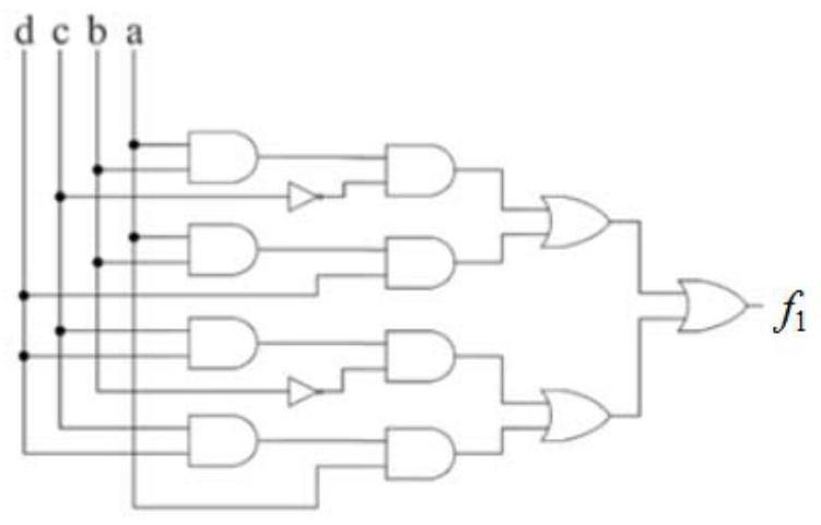
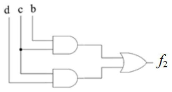
exist Figure 1a and Figure 1b In the example shown, the number of input combinations that cause erroneous output of the logic circuit is controlled to 2 input combinations. Obviously, relaxing or limiting the number of input combinations that cause erroneous output of the logic circuit will affect the simplification of the logic circuit

Method used


Image

  • Approximate simplification method of single-output combinational logic circuit
  • Approximate simplification method of single-output combinational logic circuit
  • Approximate simplification method of single-output combinational logic circuit

Examples


Embodiment 1

[0075] The first round is calculated as follows:

[0076] Step 1: Assume the single output logistic function is then f(x 1 ,x 2 ,x 3 ,x 4 ) The product term set C composed of all product terms contained in f ={0021,0201,1112,1000}. Assuming an approximation function f a (x 1 ,x 2 ,x 3 ,x 4 ) and the single-output logistic function f(x 1 ,x 2 ,x 3 ,x 4 The number of different minimum items contained in ) cannot be greater than 2, that is, H≤2.

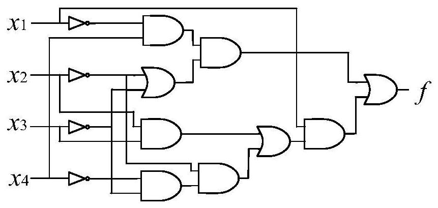
[0077] figure 2 The single output logistic function is given The corresponding circuit diagram, image 3 The single output logistic function is given The corresponding Karnaugh map.

[0078] Step 2: Define the following sets whose initial value is an empty set, denoted as C cur 、C dis 、C dis1 、C RMD 、C tmp 、C er 、C M 、C pnt and C xor .

[0079] Step 3: Choose C f The two product terms in , denoted as p i and p j , assuming p i =(0021),p j =(0201), the product term p i stored in C cur , the product...

Embodiment 2

[0109] Suppose the single-output logistic function is Figure 8 is the Karnaugh map corresponding to f. Utilize the method of the present invention to find two p in f z compliant with step 12 p z1 =(0221) and p z2 =(2112), see for details Figure 9 The Karnaugh map shown. p z1 and p z2 Each generates a C er A set of product terms, all of which are C er = {0111} and is stored to C xor , Figure 9 The square marked "T" in the Karnaugh diagram corresponds to the minimum term (0111), and the final C xor ={0111,0111}. due to C xor The two product terms in are equal, after step 14 to step 15, C xor Both product terms are deleted, so we get due to C M ={1000,0221,2112}, wherein the product term (0221) and (2112) intersect, so there is a logical "exclusive OR" relationship between the two product terms, so f can be expressed as Assuming an approximate function f of f a Satisfying H≤1, the minimum term can be delete, get obviously f a Than the original To ...


PUM


Abstract

The invention discloses an approximate simplification method for a single-output combinational logic circuit. The method comprises the steps: approximately representing a plurality of product terms asa product term under the constraint of an error rate, and deleting a specific product term, thereby achieving the simplification of a logic function; considering that a logic expression of a simple logic function often corresponds to a simple circuit structure, some logic circuits have a larger optimization space; on the premise of not influencing normal application of the logic circuit, furtheroptimization of performance such as power consumption, speed and area of the logic circuit can be realized; although the method is a single-output combinational logic circuit simplification method; however, the multi-output combinational logic circuit can be converted into a combination of a plurality of single-output circuits; therefore, the method can be popularized to the simplification of themulti-output combinational logic circuit, is suitable for the optimization of the logic circuit of which the logic function can be described by an AND / OR form logic function, is easy to program and implement, can be integrated into computer aided design, and is used for the integration and optimization of the logic circuit.

Description

technical field [0001] The invention relates to an approximate calculation technique for logic circuits, in particular to an approximate simplification method for single-output combinational logic circuits. Background technique [0002] Approximate calculation is to realize the optimization of circuit area, power consumption, delay and other performance and parameters by appropriately reducing the calculation accuracy without affecting the normal application of the circuit. At present, approximate computing has become a new and important strategy in the design of digital integrated circuits, and has been applied in some scenarios with a large amount of calculation and certain fault tolerance, such as multimedia processing, sensor data processing in the Internet of Things, data search, etc. In many ways. [0003] The logic function of a logic circuit can generally be described by a logic function, and the complexity of the logic function is closely related to the complexity ...

Claims


Application Information

Patent Timeline
IPC IPC(8): G06F30/327
CPCG06F30/327
Inventor 邹九发王伦耀夏银水储著飞
Owner NINGBO UNIV
Learn More