
CO2 trapping system based on chemical-looping combustion coupled supercritical hydrothermal reaction, and working method

A technology of chemical chain combustion and supercritical water, which is applied in the direction of combustion methods, combustion equipment, fuel supply, etc., can solve the problems of reduced cycle reaction rate, residual coke cannot fully react with oxygen carrier, etc., to reduce heat loss, reduce Possibility of poisoning, effect of reducing melting and sintering characteristics

Pending Publication Date: 2020-11-17
HUADIAN ELECTRIC POWER SCI INST CO LTD
View PDF0 Cites 2 Cited by
  • Summary
  • Abstract
  • Description
  • Claims
  • Application Information

AI Technical Summary

Problems solved by technology

[0007] The purpose of the present invention is to solve the technical problems such as the reduction of the cycle reaction rate caused by the sintering and melting of the oxygen carrier in the chemical looping combustion cycle reaction, and the inability of the residual coke to fully react with the oxygen carrier after coal pyrolysis, and provide a chemical looping combustion based CO coupled supercritical hydrothermal reaction 2 Capture system and working method

Method used


Image

  • CO2 trapping system based on chemical-looping combustion coupled supercritical hydrothermal reaction, and working method

Examples


Embodiment Construction

[0028] The present invention will be further described in detail below in conjunction with the accompanying drawings and examples. The following examples are explanations of the present invention and the present invention is not limited to the following examples.

[0029] Example.

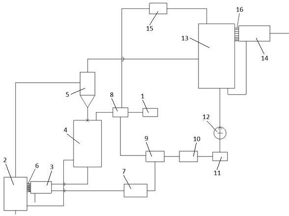
[0030] see figure 1 , in this example based on chemical looping combustion coupling supercritical hydrothermal reaction of CO 2 The capture system includes chemical looping combustion system, supercritical water oxidation system, coal water slurry system and CO 2 storage device 1.

[0031] The chemical looping combustion system includes an air reactor 2, a pyrolysis furnace 3, a fuel reactor 4, and a cyclone separator 5. The air reactor 2 includes three interfaces, which are the bottom air inlet, the side oxygen carrier inlet and the top outlet.

[0032] The pyrolysis furnace 3 has three interfaces, which are the bottom fuel inlet, the side gas product outlet and the side residual coke outlet. T...


PUM

PropertyMeasurementUnit
thicknessaaaaaaaaaa
thicknessaaaaaaaaaa

Abstract

The invention relates to a CO2 trapping system based on a chemical-looping combustion coupled supercritical hydrothermal reaction, and a working method. In an existing chemical-looping combustion cycle reaction, an oxygen carrier is sintered and melted, and consequently the cycle reaction rate is decreased. The CO2 trapping system comprises a chemical-looping combustion system which comprises an air reactor, a pyrolyzing furnace, a fuel reactor and a cyclone separator, and the pyrolyzing furnace is connected with the air reactor. The CO2 trapping system is characterized by further comprising aCO2 storage device, a coal water slurry system and a supercritical hydrothermal reaction system, wherein the coal water slurry system comprises coal grinding equipment, a water storage tank, a mixingtank, a colloid tank and a slurry storage tank, and the water storage tank, the mixing tank, the colloid tank and the slurry storage tank are sequentially connected through pipelines; and the supercritical hydrothermal reaction system comprises a high-pressure coal water slurry pump, a supercritical water oxidation reactor, a preheater and a CO2 separator, and the preheater is connected with thesupercritical water oxidation reactor. The chemical-looping combustion economy and the energy utilization efficiency are improved, and CO2 can be trapped with the low cost and low energy consumption.

Description

technical field [0001] The present invention relates to CO 2 The field of capture and fossil fuel combustion, especially involving a CO based on chemical looping combustion coupled with supercritical hydrothermal reaction 2 Capture system and working method. Background technique [0002] CO in Earth's atmosphere since industrial civilization 2 The concentration has risen sharply due to human production activities. CO 2 As a typical greenhouse gas, it directly leads to the greenhouse effect. Currently, CO 2 The emission reduction can be achieved by adjusting the energy structure and improving energy conversion and utilization efficiency. [0003] From the perspective of energy structure, since the situation that human beings use fossil energy as the main energy source will not change in the short term, especially in my country, where coal occupies an absolute dominant position from the reserve composition to the energy consumption system, how to make the energy system e...

Claims


Application Information

Patent Timeline
Patent Type & Authority Applications(China)
IPC IPC(8): F23C99/00F23K1/00C10L1/32C10L3/08
CPCF23C99/00F23K1/00C10L1/326C10L3/08Y02E20/34
Inventor 李焕龙何子春章琎李德强曹森孟劼朱锋杰李养俊张强车卫江贺室衡
Owner HUADIAN ELECTRIC POWER SCI INST CO LTD
Learn More