
Cold trap device

A cold trap and accommodating cavity technology, applied in the field of optoelectronic testing, can solve the problems of unusable low-temperature refrigeration equipment, waste of resources, and high experimental cost

Pending Publication Date: 2020-10-30
江苏鲲鹏未来光学有限公司
View PDF0 Cites 0 Cited by
  • Summary
  • Abstract
  • Description
  • Claims
  • Application Information

AI Technical Summary

Problems solved by technology

At present, since the low-temperature refrigeration equipment of different photoelectric test platforms cannot be used universally, it is necessary to repeatedly purchase and load the photoelectric test equipment of the low-temperature module in different experiments, resulting in high experimental costs and waste of resources

Method used


Image

  • Cold trap device
  • Cold trap device
  • Cold trap device

Examples


Embodiment Construction

[0035] The technical solutions in the embodiments of the present application will be described clearly and completely in conjunction with the accompanying drawings in the embodiments of the present application. Obviously, the described embodiments are part of the embodiments of the present application, rather than all of them. Based on the embodiments in this application, all other embodiments obtained by those of ordinary skill in the art without creative work shall fall within the protection scope of this application.

[0036] In the description of this application, it should be understood that the terms "center", "longitudinal", "transverse", "length", "width", "thickness", "upper", "lower", "front", " "Back", "Left", "Right", "Vertical", "Horizontal", "Top", "Bottom", "Inner", "Outer", "Clockwise", "Counterclockwise" and other directions or The positional relationship is based on the orientation or positional relationship shown in the drawings, and is only for the convenience...


PUM


Abstract

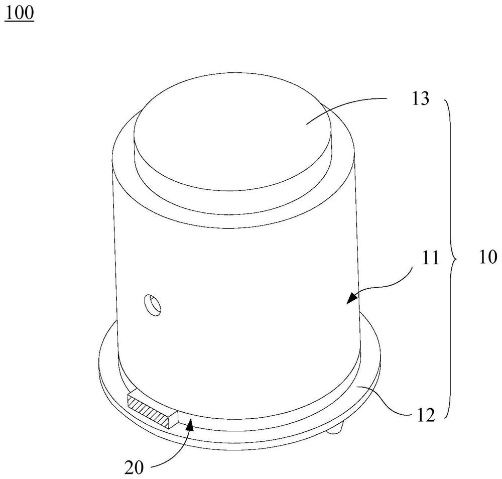
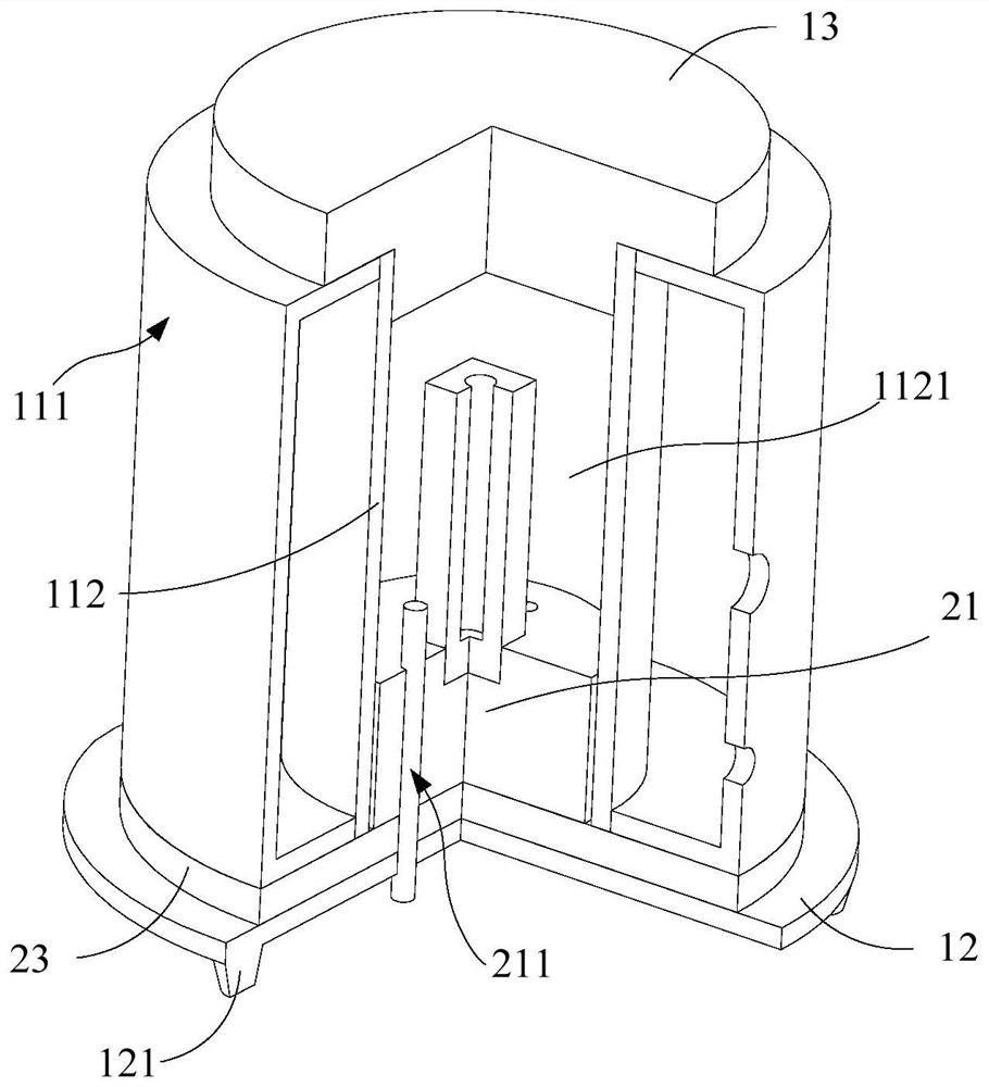
The embodiment of the invention discloses a cold trap device, which is used for a photoelectric test system and comprises a cold trap and a base assembly, the cold trap comprises a shell, the shell comprises an outer sleeve and an inner sleeve, the outer sleeve is sleeved outside the inner sleeve, the inner sleeve is provided with an accommodating cavity, and a vacuum interlayer is arranged between the outer sleeve and the inner sleeve; the base assembly comprises a sample base, a heat conduction plate and a heat insulation layer, the heat insulation layer is covered with the shell, the samplebase is arranged in the containing cavity, one end of the heat conduction plate is connected with the sample base, and the other end of the heat conduction plate is connected with external refrigeration equipment and used for adjusting the temperature in the containing cavity; wherein the cold trap further comprises a base, the base assembly is installed on the base, and the cold trap device is detachably installed on the photoelectric test system through the base.

Description

Technical field [0001] The invention relates to the technical field of photoelectric testing, in particular to a cold trap device. Background technique [0002] When performing photoelectric testing of samples, it is very important to characterize the properties of samples in a low-temperature environment. Directly lowering the temperature of the samples will cause a large amount of condensation or freezing at the samples, making it impossible to carry out photoelectric tests. In particular, if there is no atmosphere isolation near the sample, gas molecules will act as a heat transfer medium to conduct heat conduction to the low-temperature sample from the surrounding temperature, and the temperature cannot be lowered. Therefore, heat conduction isolation and water vapor isolation are the key to achieving low temperature testing. At present, since the low-temperature refrigeration equipment of different optoelectronic test platforms cannot be used universally, it is necessary to...

Claims


Application Information

Patent Timeline
Patent Type & Authority Applications(China)
IPC IPC(8): G01R31/00G01M11/02G01M11/04G05D23/22
CPCG01R31/003G01M11/0207G01M11/04G05D23/22
Inventor 赵力涛赵文涛邢晓林泉
Owner 江苏鲲鹏未来光学有限公司
Learn More