
Controllable surface nitriding device and using method thereof

A nitriding and vacuum device technology, applied in metal material coating process, coating, solid-state diffusion coating, etc., can solve the problem of uneven nitriding on the workpiece surface, uneven performance distribution, and adsorption on a certain workpiece surface. and other problems, to achieve the effect of improving mechanical properties and novel device structure

Active Publication Date: 2020-10-30
YANGZHOU UNIV
View PDF13 Cites 6 Cited by
  • Summary
  • Abstract
  • Description
  • Claims
  • Application Information

AI Technical Summary

Problems solved by technology

[0003] The purpose of the present invention is to solve the problem that when iron nitride is gradually adsorbed on the workpiece surface by glow discharge during the nitriding process, the gradually adsorbed amount of iron nitride cannot be controlled, and it is easy to cause iron nitride to be adsorbed on a certain workpiece surface. , or even a certain point on the surface of a certain workpiece, resulting in uneven nitriding on the surface of the workpiece, large deviations in the mechanical properties, anti-corrosion, and high-temperature resistance characteristics of the surface of the parts after nitriding, and uneven performance distribution. The controlled surface nitriding device and its use method can gradually absorb iron nitride on the surface of multiple circular metal parts according to the rotation direction to produce nitriding effect, which solves the problem of iron nitride in the nitriding process in the past. The problem of uncontrollable adsorption and uneven distribution can further improve the mechanical properties of the workpiece surface

Method used


Image

  • Controllable surface nitriding device and using method thereof
  • Controllable surface nitriding device and using method thereof
  • Controllable surface nitriding device and using method thereof

Examples


Embodiment Construction

[0023] The present invention will be further described below in conjunction with accompanying drawing:

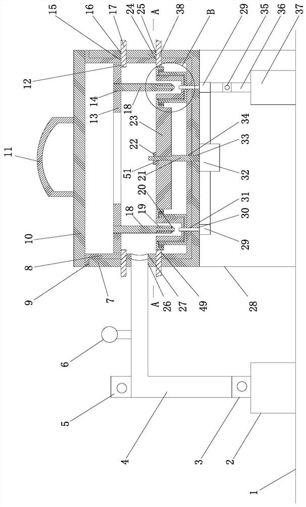
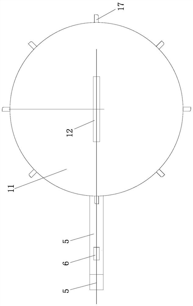
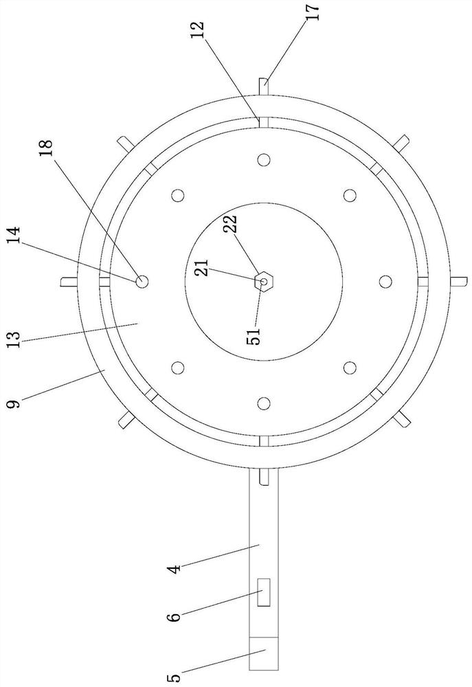
[0024] Such as Figure 1-7 As shown, a controllable surface nitriding device is composed of a vacuum device, a surface nitriding control mechanism and a nitrogen gas supply structure.

[0025] Such as Figure 1-7As shown, a controllable surface nitriding device, the vacuum device consists of a vacuum pump 2, a first solenoid valve 3, a metal pipe 4, a second solenoid valve 5, a pressure gauge 6, a vacuum chamber shell 7, an insulating inner pad 8, a gland 10. The support frame 28 is composed of; the metal pipe 4 is connected to the vacuum pump 2 through the first solenoid valve 3, the second solenoid valve 5 and the pressure gauge 6 are all set on the metal pipe 4, and the vacuum chamber shell 7 is supported on the ground 1 through the support frame 28. Above, the insulating inner pad 8 is arranged on the inner wall of the vacuum chamber shell 7, the top of the insulating...


PUM


Abstract

The invention discloses a controllable surface nitriding device and a using method thereof, and belongs to the technical field of metal material surface treatment. The device is structurally composedof a vacuum device, a surface nitriding control mechanism and a nitrogen supply structure. The device is novel in structure. By means of the device, iron nitride can be gradually adsorbed on the surfaces of a plurality of annular metal parts in the figure in a circulating mode according to the rotating direction to generate a nitriding effect, excellent surface hardening treatment can be simply applied to materials such as stainless steel, titanium and cobalt which are difficult to treat, the iron nitride can be gradually adsorbed on the surfaces of the plurality of annular metal parts in thecirculating mode according to the rotating direction to generate the nitriding effect, the problems that the adsorption amount of the iron nitride cannot be controlled and the distribution is not uniform in the nitriding process in the past are solved, and the mechanical property of the surface of a workpiece can be further improved.

Description

technical field [0001] The invention belongs to the technical field of surface treatment of metal materials, and relates to a nitriding device and a use method thereof, in particular to a controllable surface nitriding device and a use method thereof. Background technique [0002] Nitriding treatment refers to a chemical heat treatment process that makes nitrogen atoms penetrate into the surface layer of the workpiece in a certain medium at a certain temperature. The products after nitriding treatment have excellent wear resistance, fatigue resistance, corrosion resistance and high temperature resistance. At present, the commonly used surface nitriding method is to place the workpiece in the nitriding furnace and vacuumize the furnace in advance. , Connect the furnace body to the anode, the workpiece to the cathode, and a DC voltage of several hundred volts is passed between the two electrodes. At this time, the N2 gas in the furnace undergoes a brilliant discharge to form p...

Claims


Application Information

Patent Timeline
Patent Type & Authority Applications(China)
IPC IPC(8): C23C8/24
CPCC23C8/24
Inventor 秦康生陆素梅张志高吴宝伟
Owner YANGZHOU UNIV
Learn More