
Method and device for crushing waste tyre

A crushing device and technology for waste tires, applied in chemical instruments and methods, solid waste removal, tires, etc., can solve problems such as inability to eliminate iron components, and achieve the effects of simplified production process, less blade wear, flexible recycling and reuse

Inactive Publication Date: 2003-08-20
M DIA
View PDF0 Cites 0 Cited by
  • Summary
  • Abstract
  • Description
  • Claims
  • Application Information

AI Technical Summary

Problems solved by technology

In addition, the waste tires treated in this way are crushed very finely, but there are many iron components buried inside the rubber that cannot be adsorbed on the magnet, so after passing through a magnetic separator, the iron components cannot be completely eliminated

Method used


Image

  • Method and device for crushing waste tyre
  • Method and device for crushing waste tyre
  • Method and device for crushing waste tyre

Examples


Embodiment Construction

[0032] The crushing device for waste tires according to the present invention will now be specifically described with reference to the accompanying drawings.

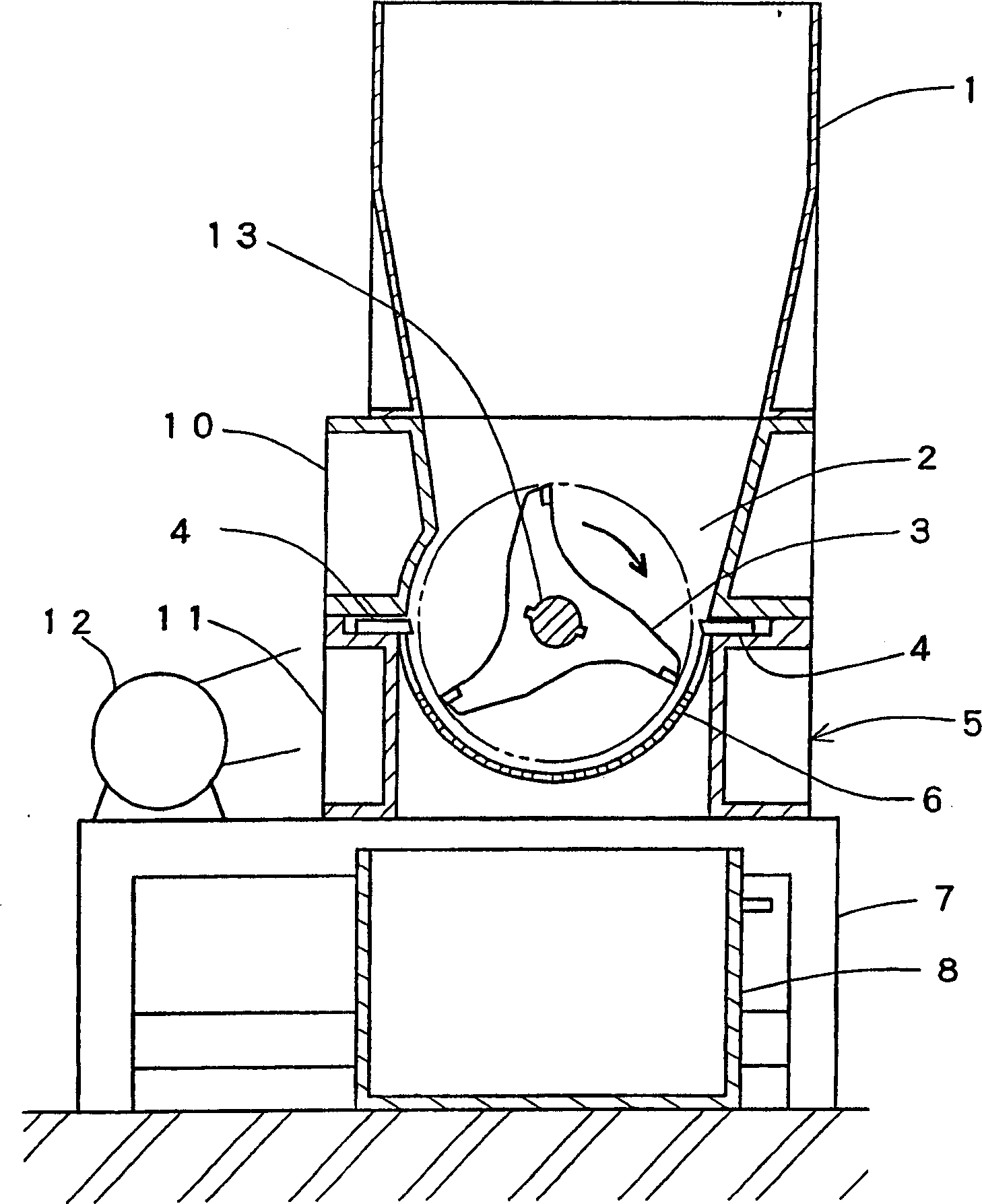
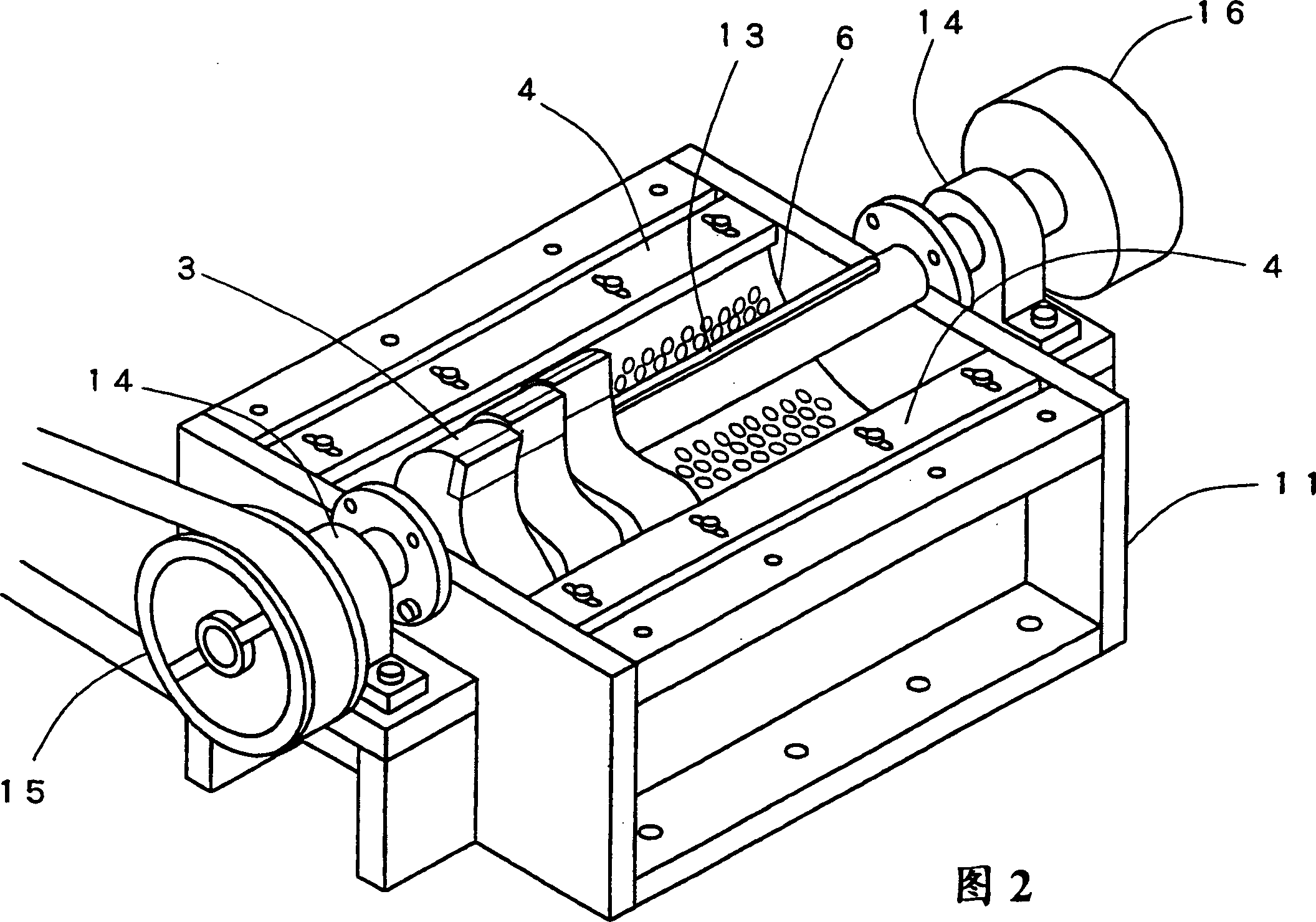
[0033] figure 1 1 is a sectional view of the pulverizing device, and FIG. 2 is a perspective view of the main parts of the pulverizing device. This crushing device is composed of a hopper 1 for throwing waste tire chips, a main body 5 with a rotary knife 3 for stirring and crushing the tire chips in a box 2 communicated with the outlet of the hopper, and a base 7 for placing them. .

[0034] The rotary cutter 3 is a tool in which a plurality of superhard cutting bits are brazed at three positions at the vertices of a substantially triangular thick plate-shaped tool holder, through a main shaft 13 with pins embedded therein, and adjacent blades The state of slightly shifted phase is fixed and constituted. The reason why the rotating knife is separated in this way is to distribute the resistance applied to the blade. ...


PUM


Abstract

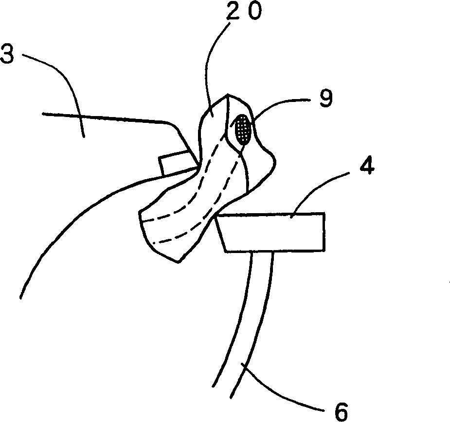
The present invention provides a method and an apparatus for crushing and pulverizing tire chips roughly crushed to a size of 10 cm in length by completely separating to rubber components from iron components in a single crushing process. It is intended to extensively simplify the process to produce rubber powder from waste tires and to promote material recycling of the used tires. The method comprises the steps of catching the tire chips between monoaxial rotary blades 3 rotated within a casing 2 and fixed blades 4 and 4 fixed and arranged at opposed positions and maintaining a gap slightly larger than diameter of a piano wire 9 contained in the tires, rupturing only the rubber components without cutting piano wires and steel fibers, tearing and withdrawing rubber components by rotation of the rotary blade 3, and crushing while separating rubber components from iron components.

Description

technical field [0001] The invention relates to a crushing method and device for waste tires, which are used for separating iron components such as piano wires and steel fibers embedded in the tires, and at the same time reusing the rubber easily. Background technique [0002] At present, more than 100 million waste tires are produced in China every year. The piles of waste tires piled up in open spaces in the suburbs are not only detrimental to sight, but also have the danger of causing major accidents due to natural fires. It is generally believed that the recycling rate of waste tires exceeds 90%, and it is the leader in waste utilization among industrial wastes. However, it has to be said that the actual situation is quite different from this view. If you look at the recycling of waste tires, more than half of them are heat utilization, that is, burning waste tires to generate electricity or using them as fuel when sintering cement, which can be said to be nothing more ...

Claims


Application Information

Patent Timeline
Patent Type & Authority Patents(China)
IPC IPC(8): B02C18/00B02C18/14B02C18/18B02C23/16B29B17/02B29B17/04
CPCB29B17/0412B29B17/02B29K2021/00B02C18/146B29B2017/0476B29L2030/00Y10S241/31B02C2023/165B29B2017/0448B02C2201/04B29K2705/12Y02W30/52Y02W30/62B02C18/06B29B17/04
Inventor 森诚一
Owner M DIA
Learn More