Method and equipment for recycling ammonia gas in production of ammonium paratungstate
A technology of ammonium paratungstate and ammonia gas, which is applied in the field of tungsten smelting and processing, can solve the problem of low reuse rate of liquid ammonia, and achieve the effect of complete recovery and simple treatment
- Summary
- Abstract
- Description
- Claims
- Application Information
AI Technical Summary
Problems solved by technology
Method used
Image
Examples
Embodiment 1
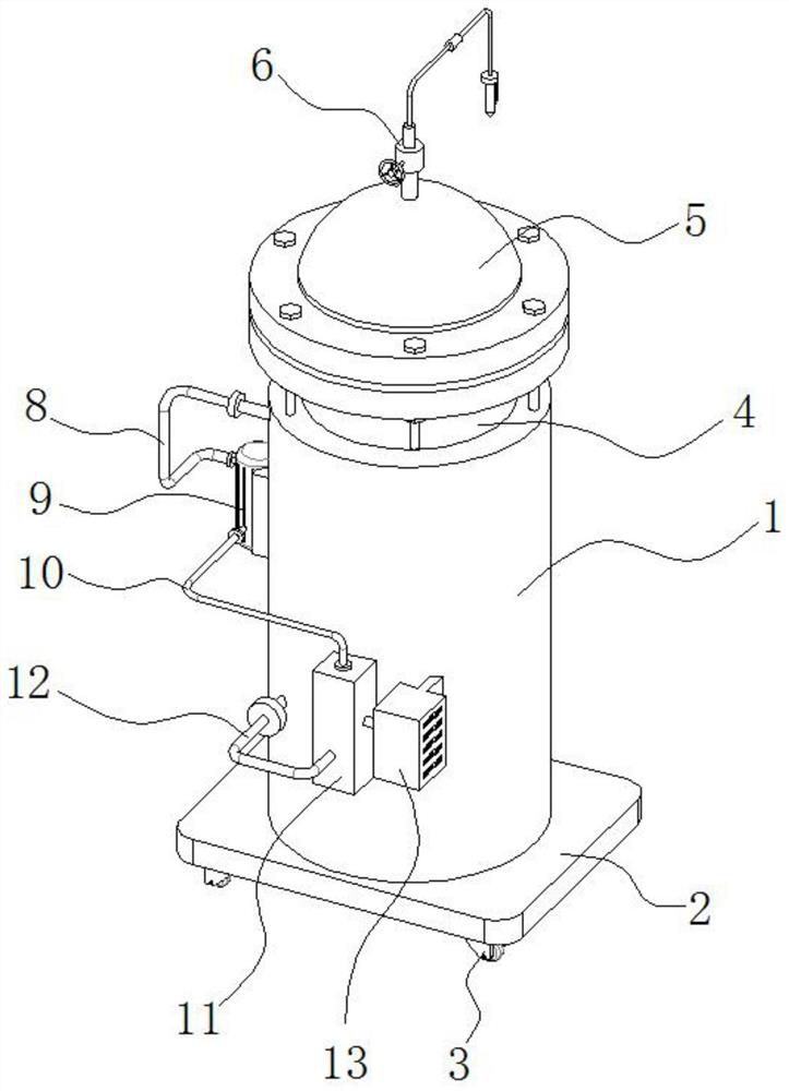
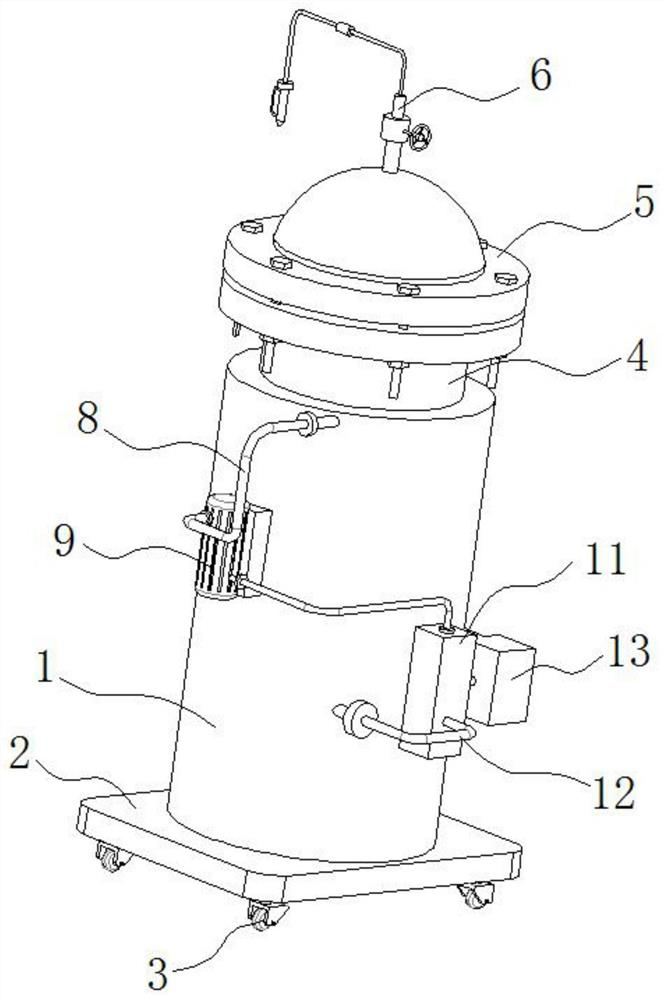
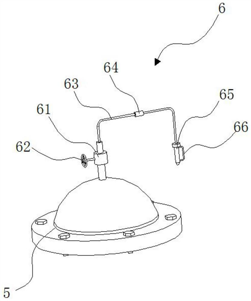
[0031] refer to Figure 1-5 , a method for recycling ammonia in the production of ammonium paratungstate, comprising the following steps;
[0032] Step 1: Connect the crystallization pot in the process of producing ammonium paratungstate and the outlet of the rotary furnace in the process of producing yellow and blue tungsten in parallel, and use the induced draft fan to send the ammonia generated in the two devices into the rectification tower for preliminary gas-liquid separation;
[0033] Step 2: Transfer the ammonia gas from preliminary gas-liquid separation in step 1 into a condensation tank for thorough gas-liquid separation to obtain ammonia gas, then transfer 73-77% of the obtained ammonia gas to a spray adsorption tower, and use hydrochloric acid to Ammonia is sprayed and adsorbed to obtain ammonium chloride solution;
[0034] Step 3: Collect the ammonia gas sprayed in step 2 in a container, then pump the ammonium chloride solution in the container into a Venturi dev...
Embodiment 2
[0041] refer to Figure 1-7 , as another preferred embodiment of the present invention, the difference from Embodiment 1 is that the condensate storage tank 11 includes a box body 111, a first filter screen 112 and a second filter screen 113, and the first filter screen 112 and the second filter screen The net 113 is installed in parallel in the first filter net 112 and the second filter net 113; the first filter net 112 and the second filter net 113 remove impurities in the condensate to ensure rapid cooling.
[0042] The bottom of the box body 111 is fixedly installed with a liquid inlet pipe 12, and the liquid inlet pipe 12 is connected with the inlet end of the cooling coil 42; One end is fixedly installed with air cooler 132, and the outlet end of air cooler 132 is equipped with dust filter net 133, and one side of dust filter net 133 is fixedly installed with deflector 134, and the outlet end of deflector 134 is equipped with air guide pipe 135, guides The air duct 135 ...
Embodiment 3
[0044] refer to Figure 1-8 , as another preferred embodiment of the present invention, the difference from Embodiment 1 or Embodiment 2 is that a buffer assembly 7 is installed under the tank body 41, and the buffer assembly 7 includes a support seat 71, which is fixedly installed inside the housing 1 A plurality of springs 73 are fixedly mounted on the inner side of the support seat 71, and a buffer plate 72 is fixedly installed on the top of the spring 73, and the buffer plate 72 is in conflict with the bottom of the tank body 41. The function of the design of the buffer assembly 7 is that the buffer plate 72 can ensure that the tank body 41 will not shake greatly during transportation, so as to avoid safety accidents.
PUM
 Abstract
Description
Claims
Application Information
 - R&D Engineer
- R&D Manager
- IP Professional
- Industry Leading Data Capabilities
- Powerful AI technology
- Patent DNA Extraction
Browse by: Latest US Patents, China's latest patents, Technical Efficacy Thesaurus, Application Domain, Technology Topic, Popular Technical Reports.
© 2024 PatSnap. All rights reserved.Legal|Privacy policy|Modern Slavery Act Transparency Statement|Sitemap|About US| Contact US: help@patsnap.com


