
Ultraviolet LED with polarized doped composite polar surface electron blocking layer

An electron blocking layer, polarization doping technology, applied in circuits, electrical components, semiconductor devices, etc., can solve the problems of crystal quality decline, current leakage, low mobility and effective mass, etc., to reduce the generation of dislocation defects, The effect of reducing the degree of band bending and avoiding the degradation of crystal quality

Active Publication Date: 2020-08-28
SOUTHEAST UNIV
View PDF7 Cites 5 Cited by
  • Summary
  • Abstract
  • Description
  • Claims
  • Application Information

AI Technical Summary

Problems solved by technology

For AlGaN-based UV-LEDs, the hole concentration is very low, coupled with the low mobility of holes, resulting in low efficiency of hole injection into the quantum well active region; while electrons have higher mobility and smaller The effective mass, especially in the case of large current injection, is easy to overcome the limitation of the quantum well and reach the p-type region for non-radiative recombination with holes, so it will cause serious current leakage
[0003] like figure 2 As shown, the AlGaN-based UV-LED prepared in the prior art includes a substrate 201, a low-temperature AlN nucleation layer 202, a high-temperature AlN intermediate layer 203, an undoped AlGaN buffer layer 204, and an n-type AlGaN Layer 205, Al x1 Ga 1- x1 N / Al x2 Ga 1-x2 N multi-quantum well active region 206, metal polar surface Al x3 Ga 1-x3 N electron blocking layer 207 and p-type AlGaN layer 208, n-type ohmic electrode 209 and p-type ohmic electrode 210 respectively arranged on n-type AlGaN layer 205 and p-type AlGaN layer 208, wherein the metal polar surface p-type AlGaN electron blocking Layer 208 has a higher valence band barrier to prevent holes from being injected into the multi-quantum well active region; due to the larger voltage generated by the larger lattice mismatch between the last quantum well barrier and the electron blocking layer The influence of the electric polarization electric field will cause the energy band at the interface of the heterojunction to bend, which will further block the injection of holes.
[0004] In order to effectively reduce electron leakage and improve hole injection efficiency, some researchers have proposed to use AlGaN electron blocking layer with graded Al composition, p-type superlattice structure electron blocking layer, etc. to replace the single Al component of the prior art. The metal polar surface p-type AlGaN electron blocking layer, but still can not satisfactorily solve the following problems: 1) The more obvious the electron blocking effect of the electron blocking layer, the lower the hole injection efficiency; 2) The electron blocking layer and the multi-quantum well active The lattice mismatch between regions is large, which causes the energy band at the heterojunction interface to bend and also easily causes the generation of dislocation defects; 3) There is still a large polarization electric field in the multi-quantum well active region , so that the distribution of carriers in the active region is not uniform
However, simply relying on increasing the doping concentration of Mg to increase the hole concentration will lead to a serious decline in crystal quality, which in turn affects the luminous efficiency of UV-LEDs.

Method used


Image

  • Ultraviolet LED with polarized doped composite polar surface electron blocking layer
  • Ultraviolet LED with polarized doped composite polar surface electron blocking layer

Examples


Embodiment Construction

[0018] The present invention will be further described in detail below in conjunction with the accompanying drawings and specific embodiments. It should be understood that the embodiments described here are only used to specifically explain the present invention, and are not used to limit the scope of the claims of the present invention.

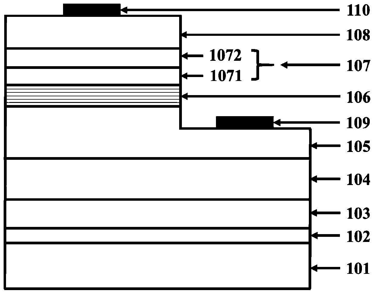
[0019] like figure 1 , a kind of ultraviolet LED with polarization-doped composite polar surface electron blocking layer of the present invention, comprising: c-plane sapphire substrate 101, low-temperature AlN nucleation layer 102, high-temperature AlN intermediate layer 103, Non-doped AlGaN buffer layer 104, n-type AlGaN layer 105, Al x1 Ga 1-x1 N / Al x2 Ga 1-x2 N multi-quantum well active region 106, polarization-doped compound polar surface electron blocking layer 107 and p-type Al x5 Ga 1-x5 N layer 108, n-type AlGaN layer 105 is provided with n-type ohmic electrode 109, p-type Al x5 Ga 1-x5 A p-type ohmic electrode 110 is set o...


PUM

PropertyMeasurementUnit
Thicknessaaaaaaaaaa
Thicknessaaaaaaaaaa
Thicknessaaaaaaaaaa

Abstract

The invention discloses an ultraviolet LED with a polarized doped composite polar surface electron blocking layer. The device comprises a substrate arranged in sequence from bottom to top, the devicecomprises a low-temperature AIN nucleating layer, a high-temperature AlN intermediate layer, a non-doped AlGaN buffer layer, an n-type AlGaN layer, an Alx1Ga (1-x) 1N / Alx2Ga (1-x) 2N multi-quantum well active region, a polarization doped composite polar surface electron blocking layer and a p-type Alx5Ga (1-x) 5N layer, an n-type ohmic electrode is arranged on the n-type AlGaN layer; wherein a p-type ohmic electrode is arranged on the p-type Alx5Ga1-x5N layer, and the polarization doped composite polar surface electron barrier layer comprises a nitrogen polar surface p-type Alx3Ga1-x3N electron barrier layer and a metal polar surface p-type Alx4Ga1-x4N electron barrier layer which are arranged from bottom to top. The polarized doped composite polar surface electron barrier layer has higherelectron barrier layer hole concentration, and hole injection of the p-type Alx5Ga1-x5N layer is facilitated; lattice mismatch between the active region and the electron blocking layer is reduced, and the crystal quality of the epitaxial layer is improved; the radiation recombination efficiency of electron holes in an active region is improved, and the light-emitting efficiency of the ultravioletlight-emitting diode is improved.

Description

technical field [0001] The invention relates to the manufacturing field of semiconductor optoelectronic materials and devices, in particular to an ultraviolet LED with a polarization-doped composite polar surface electron blocking layer. Background technique [0002] Ultraviolet light-emitting diodes (UV-LEDs) based on III-nitride wide bandgap semiconductor materials have broad application prospects in the fields of sterilization, polymer curing, biochemical detection, non-line-of-sight communication, and special lighting. The light source mercury lamp, UV-LED has the advantages of mercury-free environmental protection, small and portable, low power consumption, low voltage and so on. For AlGaN-based UV-LEDs, the hole concentration is very low, coupled with the low mobility of holes, resulting in low efficiency of hole injection into the quantum well active region; while electrons have higher mobility and smaller Especially in the case of high current injection, it is easy ...

Claims


Application Information

Patent Timeline
IPC IPC(8): H01L33/14H01L33/06
CPCH01L33/14H01L33/145H01L33/06
Inventor 张雄陈斌胡国华崔一平
Owner SOUTHEAST UNIV
Learn More