
Grouting consolidation method for large-diameter concrete pipeline lining fiber grid

A technology of fiber mesh and concrete, applied in the direction of pipes, pipe components, rigid pipes, etc., can solve the problems of low efficiency of pipe strength and rigidity improvement, difficulty in guaranteeing long-term performance, and high requirements for pasting technology, so as to avoid the phenomenon of hollow drums in reinforcement, Improve pipeline transportation capacity and eliminate the effect of waterproofing process

Active Publication Date: 2020-08-14
江苏绿材谷新材料科技发展有限公司
View PDF11 Cites 3 Cited by
  • Summary
  • Abstract
  • Description
  • Claims
  • Application Information

AI Technical Summary

Problems solved by technology

The outsourcing concrete method requires excavation, and local pouring of concrete on the outside of the pipe will cause structural unevenness along the pipe axis, which is not conducive to the stress of the pipe
The sleeve grouting method has complex procedures, high cost, greatly reduced pipe diameter, and long-term performance is difficult to guarantee
The lining fiber cloth reinforcement method is inefficient in improving the strength and stiffness of the pipeline, and it takes a long time to reinforce large areas. It needs to paste fiber materials in multiple layers. The paste process requires high requirements and directly affects the reinforcement effect.

Method used


Image

  • Grouting consolidation method for large-diameter concrete pipeline lining fiber grid
  • Grouting consolidation method for large-diameter concrete pipeline lining fiber grid
  • Grouting consolidation method for large-diameter concrete pipeline lining fiber grid

Examples


Embodiment

[0035] Embodiment: A fiber grid grouting reinforcement method for the lining of large-diameter concrete pipes.

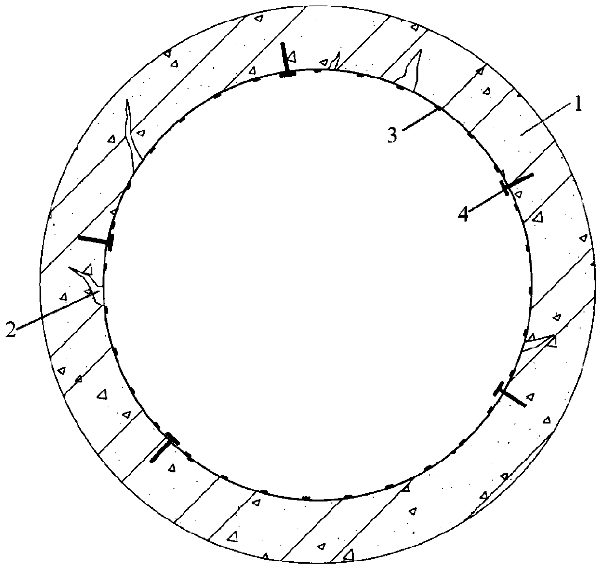
[0036] Pipeline 1 is a concrete circular pipe with a diameter of more than 1m that can enter people, or a pipe with a height of more than 1m and a width of more than 0.9m that can enter people. The long-term use of the pipeline will lead to the cracking and damage of the pipeline concrete, forming structural cracks2.

[0037] The specific reinforcement method includes the following steps:

[0038] (1) Firstly, manually survey the inside of the pipeline 1, remove foreign matter and garbage in the pipeline, and chisel out the deteriorated part of the concrete on the pipe wall; then use a high-pressure water gun to clean the surface of the inner wall of the pipeline 1 and keep it dry;

[0039] (2) Put the fiber mesh 3 cut according to the designed size into the pipeline 1 through the manhole; When bolting, the edge of the gasket should be aligned with the edge of the...


PUM

PropertyMeasurementUnit
diameteraaaaaaaaaa

Abstract

The invention discloses a grouting consolidation method for a large-diameter concrete pipeline lining fiber grid. The grouting consolidation method comprises the following steps: clearing the inner surface of a to-be-consolidated concrete pipeline; mounting a fiber grid on the inner surface of the processed pipeline, and temporarily fixing the fiber grid by the device; mounting a waterproof surface layer at the outer side of the mounted fiber grid, and using the device to temporarily fix the waterproof surface layer; grouting mortar into a gap between the paved fiber grid and the waterproof surface layer; and after mortar curing is accomplished, dismounting a waterproof surface layer fixing device, and welding a jointing seam exposed by the surface layer. The effect of the fiber grid, themortar and the waterproof surface layer is sufficiently brought into play. The method disclosed by the invention can be adopted to remarkably improve structure bearing ability, also can form an effective waterproof layer on the surface of the structure, does not need excavation, is quick in construction, and is small in influences on production and life.

Description

technical field [0001] The invention relates to the technical field of structural reinforcement, in particular to a method for reinforcing a damaged pipeline. It is especially suitable for long-distance and large-diameter underground concrete damaged pipelines, using fiber mesh to improve the mechanical performance of the structure and achieve reinforcement and waterproof effects. Background technique [0002] After the long-term operation of the urban underground concrete pipeline system, due to design defects, harsh environment and accidental disasters and other factors, the concrete of the pipeline will be cracked and damaged, and the working performance will gradually deteriorate, causing serious economic losses. For the above-mentioned damaged pipelines, effective reinforcement and repair are required to restore the original bearing capacity and ensure the normal working performance of the pipelines. [0003] Commonly used reinforcement and repair methods for large-dia...

Claims


Application Information

Patent Timeline
Patent Type & Authority Applications(China)
IPC IPC(8): F16L55/164F16L9/08F16L58/10E01F5/00
CPCE01F5/005F16L9/08F16L55/164F16L58/1009
Inventor 吴智深汪昕陶甲贺卫东
Owner 江苏绿材谷新材料科技发展有限公司
Learn More