Eureka AIR delivers breakthrough ideas for toughest innovation challenges, trusted by R&D personnel around the world.

Metal corrugated pipe manufacturing and machining process

A metal bellows and processing technology, which is used in metal processing equipment, manufacturing tools, grinding workpiece supports, etc., can solve the problems of difficulty in grinding, long bellows length, and inability to discharge completely, and achieve the effect of improving grinding efficiency.

Active Publication Date: 2020-08-11
郭亚亚
View PDF8 Cites 12 Cited by
  • Summary
  • Abstract
  • Description
  • Claims
  • Application Information

AI Technical Summary

Problems solved by technology

It is mainly used for non-concentric axial transmission with small bending radius, irregular turning, expansion and contraction, or absorption of thermal deformation of pipelines, etc., where it is not convenient to use fixed elbows to connect pipelines, or to connect pipelines with equipment connection use
[0003] After the processed bellows are segmented, the inner wall needs to be inspected to see if there are foreign objects including process scale accumulated in the bellows. Therefore, the bellows needs to be further refined, and the foreign matter or process scale on the inner wall should be polished and removed. ; The existing grinding device has the following disadvantages: one, the inner wall of the metal bellows is wavy, and the troughs are not easy to be polished when grinding, resulting in foreign matter or dirt still in the bellows; The foreign matter or scale easily remains in the trough of the bellows when it is removed, and cannot be completely discharged

Method used


Image

  • Metal corrugated pipe manufacturing and machining process
  • Metal corrugated pipe manufacturing and machining process
  • Metal corrugated pipe manufacturing and machining process

Examples


Embodiment Construction

[0036] The embodiments of the present invention will be described in detail below with reference to the accompanying drawings, but the present invention can be implemented in many different ways defined and covered by the claims.

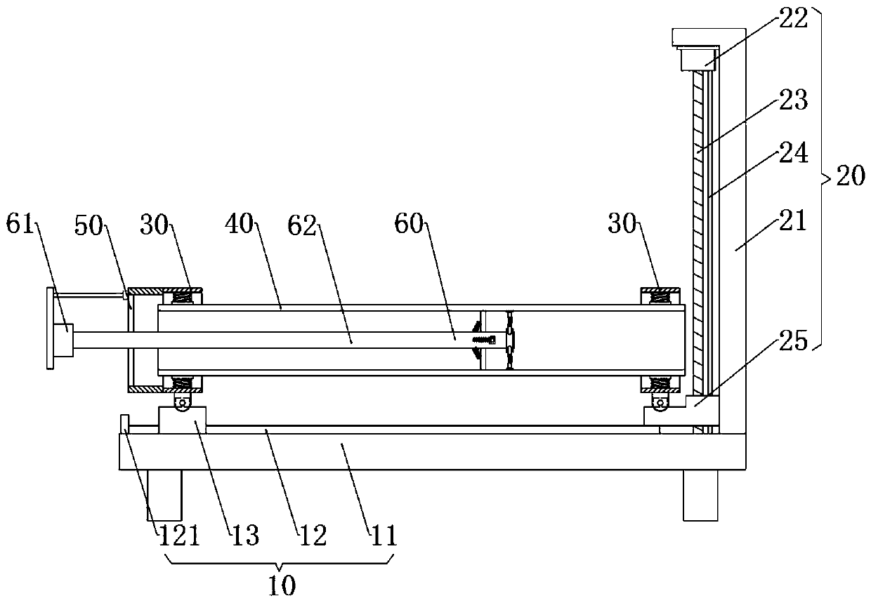
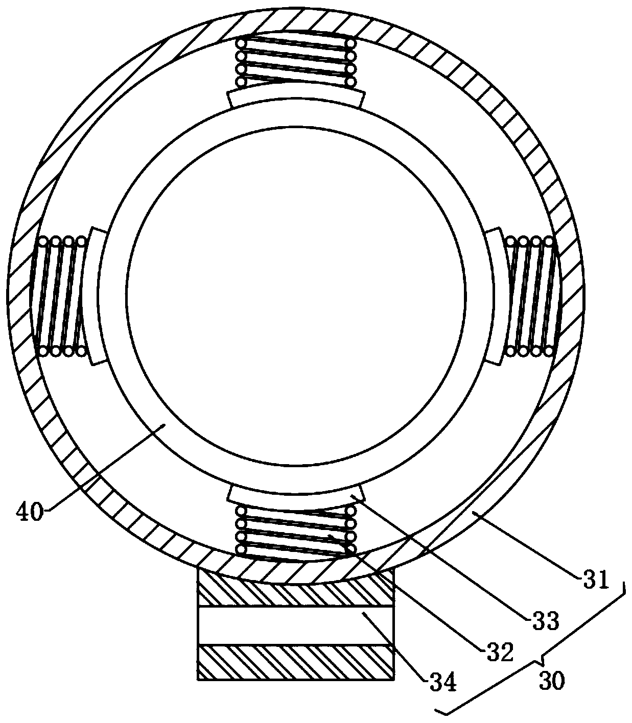
[0037] Such as figure 2 As shown, a metal bellows manufacturing process, the bellows manufacturing process adopts the following processing machinery, the processing machine includes a base 10 and a lifting device 20 arranged on the top side of the base 10, and the top of the base 10 is horizontally provided with corrugated The pipe body 40, the base 10 and the lifting device 20 are all equipped with a fixing device 30 for fixing the corrugated pipe body 40, and one side of the fixing device 30 installed on the base 10 is provided with a mounting frame 50, and the side of the mounting frame 50 A grinding device 60 penetrating through the corrugated pipe body 40 is installed on the wall;

[0038]The base 10 includes a bottom plate 11 and legs arrang...


PUM


Abstract

The invention relates to a metal corrugated pipe manufacturing and machining process. The metal corrugated pipe manufacturing and machining process adopts the following machining machinery. The machining machinery comprises a base and a lifting device arranged on one side of the top of the base, wherein a corrugated pipe body is arranged above the base; fixing devices are mounted on the base and the lifting device correspondingly; a mounting frame is arranged on one side of the fixing device mounted on the base; and a grinding device penetrating through the corrugated pipe body is mounted on the side wall of the mounting frame. According to the metal corrugated pipe manufacturing and machining process, the inclination of a round rod is changed through stretching and retracting of a secondspring, thus the distance between grinding heads and a first rotary shaft is changed, and the grinding heads in different planes can conduct comprehensive grinding on wave crests and wave troughs of ametal corrugated pipe; the grinding heads conduct revolution and rotation simultaneously, so that the grinding efficiency is improved; and the fixing device at one end of the corrugated pipe is driven by the lifting device to move, thus the corrugated pipe is in an inclined state, ground dirt can fall down conveniently, and meanwhile, foreign matter remaining at the wave troughs is wiped away through cooperation of a cleaning mechanism.

Description

technical field [0001] The invention relates to the technical field of bellows processing, in particular to a metal bellows manufacturing process. Background technique [0002] Metal bellows is a pipe that looks like a regular wave. Commonly used metal bellows include carbon steel and stainless steel, as well as steel-lined plastic and aluminum. It is mainly used for non-concentric axial transmission with small bending radius, irregular turning, expansion and contraction, or absorption of thermal deformation of pipelines, etc., where it is not convenient to use fixed elbows to connect pipelines, or to connect pipelines with equipment connection use. [0003] After the processed bellows are segmented, the inner wall needs to be inspected to see if there are foreign objects including process scale accumulated in the bellows. Therefore, the bellows needs to be further refined, and the foreign matter or process scale on the inner wall should be polished and removed. ; The exis...

Claims


Application Information

Patent Timeline
Patent Type & Authority Applications(China)
IPC IPC(8): B24B27/033B24B27/00B24B5/40B24B55/06B24B41/06B24B47/12B24B45/00B24B41/04B08B9/045
CPCB24B27/033B24B27/0076B24B5/40B24B55/06B24B41/067B24B47/12B24B45/006B24B41/04B08B9/045Y02P70/10
Inventor 郭亚亚江恰
Owner 郭亚亚
Why Eureka
Eureka Blog
Learn More