Completion technology method for sidetracked well
A side drilling and drill pipe technology, which is applied in the field of oil and gas field exploration and development, can solve the problems of water-blocking oil production, casing damage on the upper part of the opening point, etc., and achieve the effect of improving the pressure bearing capacity.
- Summary
- Abstract
- Description
- Claims
- Application Information
AI Technical Summary
Problems solved by technology
Method used
Image
Examples
no. 1 approach
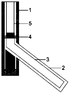
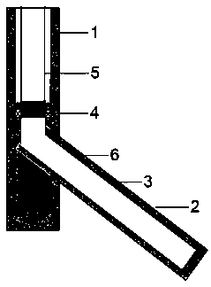
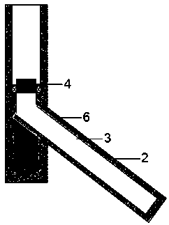
[0038] The first embodiment of the present invention relates to a sidetracking well completion method, such as Figure 1-Figure 5 shown, including the following steps:
[0039] S1. Connect the drill pipe 5, the liner suspension and tie-back integrated tool 4, and the small-diameter casing 3 sequentially from top to bottom, and lower them into the sidetracking wellbore 2;
[0040] S2, injecting cement 6 through the drill pipe 5 to carry out the cementing operation, and pulling out the drill pipe 5 after the cementing operation is completed;
[0041] S3, carry out the well flushing operation;
[0042] S4. Connect the sealing cannula 7 with the tie-back casing 8 and lower it into the wellbore, and insert the sealing cannula 7 into the tie-back barrel 4.3 reserved after the liner suspension and tie-back integrated tool 4 is discarded, and carry out Staged fracturing construction.
[0043] In the present invention, an integrated tool for liner suspension and tie-back is installe...
no. 2 approach
[0045] On the basis of the above-mentioned embodiments, such as Figure 7 As shown, the tailpipe suspension and tie-back integrated tool 4 includes a central pipe 4.4, the two ends of the central pipe 4.4 are respectively connected with an upper joint 4.1 and a lower joint 4.9, and the outside of the central pipe 4.4 is from top to bottom Tie-back barrel 4.3, rubber barrel 4.5, liquid cylinder 4.6, vertebral body 4.7 and slips 4.8 are set sequentially. The outer lower end of 4.1 is connected; between the liquid cylinder 4.6 and the central tube 4.4, there is an upper piston for pushing the rubber cylinder 4.5 to move, and between the liquid cylinder 4.6 and the central tube 4.4, there is also a lower piston for pushing the vertebral body 4.7 to move. There is a gap between the upper piston and the lower piston, and the central pipe 4.4 is provided with a pressure transmission hole at the gap.
[0046] Further, the lower part of the upper joint 4.1 is provided with a locking p...
no. 3 approach
[0050] This embodiment provides a sidetracking well completion method, such as Figure 1-Figure 6 shown, including the following steps:
[0051] S1, refer to figure 1 After connecting the drill pipe 5, the integrated tool for tailpipe suspension and tie-back 4, and the small-diameter casing 3 (diameter 88.9-114.3cm) from top to bottom in sequence, run them into the side drilled on the inside of the original well casing 1. Drill in the wellbore 2, and make the liner suspension and tie-back integrated tool 4 above the window opening point;
[0052] S2. Calculate the amount of cement needed for cementing according to the size of the outer annular space of the small-diameter casing 3, inject cement from the drill pipe 5, and after the cement injection is completed, put a cementing plug into the wellhead and continue to inject active water. When the plug is pumped to the bottom of the artificial well by liquid, the cement has filled the outer annular space of the small-diameter c...
PUM
 Abstract
Description
Claims
Application Information
 - R&D Engineer
- R&D Manager
- IP Professional
- Industry Leading Data Capabilities
- Powerful AI technology
- Patent DNA Extraction
Browse by: Latest US Patents, China's latest patents, Technical Efficacy Thesaurus, Application Domain, Technology Topic, Popular Technical Reports.
© 2024 PatSnap. All rights reserved.Legal|Privacy policy|Modern Slavery Act Transparency Statement|Sitemap|About US| Contact US: help@patsnap.com


