Rubber cleaning equipment for airport runway

An airport and rubber technology, which is applied in the field of airport runway rubber cleaning equipment, can solve the problems of difficulty in recovery, damage to the engine, and hidden safety hazards.

Pending Publication Date: 2020-07-28
北京华威智远量子科技有限公司
View PDF10 Cites 3 Cited by
  • Summary
  • Abstract
  • Description
  • Claims
  • Application Information

AI Technical Summary

Problems solved by technology

The problem is that the metal microbeads are difficult to recover in rainy and snowy weather, and the residual metal microbeads are sucked into the engine, which will damage the engine and cause safety hazards
The problem is that under the increasingly stringent environmental protection requirements, chemical preparations will gradually withdraw from the stage of history because the impact on the surrounding environment must be considered.

Method used


Image

  • Rubber cleaning equipment for airport runway
  • Rubber cleaning equipment for airport runway

Examples


Embodiment 1

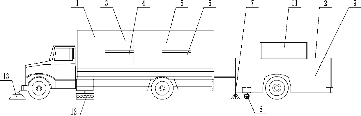
[0030] Such as figure 1 As shown, a rubber cleaning equipment for an airport runway includes a carrier vehicle 1, a trailer 2, a control center 3 installed in the carrier vehicle 1, an ion generator 4, an air separator 5, a generator 6 and a vehicle installed at the bottom of the trailer 2 The ion jet injection device 7 at the end, the dust collection device 8 and the dust box 9 inside the trailer 2, the control center includes two parts, the main control and calculation part is the control center 3, located in the carrier vehicle 1, the ion jet injection device 7, The controller 11 of the dust collection device 8 is located on the trailer 2, and acts in conjunction to control the operation of the ion generator 4, the air separator 5 and the ion jet injection device 7, and the generator 6 supplies power for the entire equipment, because each element There is only a connection relationship or an electrical signal transmission relationship between devices, and there is no specif...

Embodiment 2

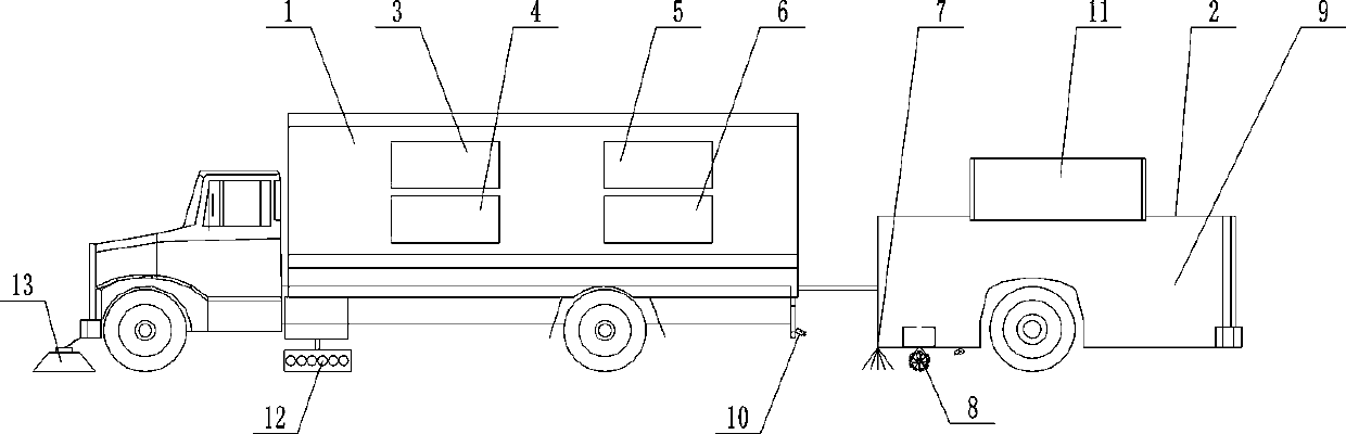
[0039] Such as figure 2 As shown, in order to improve the degree of automation, a video camera 10 is installed at the bottom of the car body, and the video camera 10 is distributed on the front and rear sides of the ion jet injection device. The video camera 10 is connected to the control center 3 for collecting road surface rubber images .

[0040]After analyzing the collected image information, for example, the following situations are obtained: no rubber layer on the road surface, a small amount of rubber layer on the road surface, and a large amount of rubber layer on the road surface. After obtaining these information, the control center 3 adjusts the ion The flow rate of the jet injection device, the efficiency of the air separator and the ionizer.

[0041] In other embodiments, in order to facilitate the walking of the vehicle while ensuring the effectiveness of the jet, the ion jet injection device can be installed on the vehicle body through an electronically contro...


PUM


Abstract

The invention provides rubber cleaning equipment for an airport runway. The equipment comprises a vehicle body, a control center, an ion generator, an air separator and a generator installed in the vehicle body, and an ion jet injection device installed at the bottom end of the vehicle body. The control center is used for controlling the operation of the ion generator, the air separator and the ion jet injection device; the ion generator is matched with the air separator to generate high-energy ions; the ion jet injection device is connected with the ion generator to inject out high-energy ions; the generator supplies power to the whole equipment; the generated high-activity plasma-state oxygen and rubber on the road surface are subjected to a violent chemical reaction which is mainly oxidation reaction; with oxidation and gasification of an accumulated rubber layer, rubber is rapidly stripped from a pavement to achieve a clearing effect, then cleaning work is carried out through accessory equipment of equipment, clearing can be completed, the pavement cannot be damaged, pollution to the environment cannot be caused, there is no residue, and rubber cleaning equipment is clean, environmentally friendly and efficient.

Description

technical field [0001] The invention relates to the field of airport cleaning, in particular to a rubber cleaning equipment for airport runways. Background technique [0002] The rubber left on the runway by aircraft take-off and landing has always been an important factor threatening the safety of aircraft take-off and landing. [0003] When aircraft tires land at high speed due to frictional contact with the surface of the runway, high temperature is caused. The high temperature causes the tire rubber to melt instantly to form a rubber melt and adhere to the texture of the runway surface. With the increase of friction times and the passage of time, the road The surface rubber layer is continuously piled up and thickened. The accumulated rubber layer reduces the friction coefficient of the runway surface and affects the braking performance of the aircraft. Especially when the road surface is wet and slippery, the viscosity of the rubber on the runway reduces the friction fo...

Claims


Application Information

Patent Timeline
IPC IPC(8): E01H1/08E01H1/14
CPCE01H1/0863E01H1/0872E01H1/14
Inventor 廖尚武王照洋刘仁武王涛陈晨王毅
Owner 北京华威智远量子科技有限公司
Why Eureka
Try Eureka