An artificial island structure for relay extension of floating tunnel

A technology of floating tunnels and artificial islands, applied in the field of underwater floating tunnels, can solve the problems of high cost, difficult to predict comfort and safety risks, displacement or shaking of tunnels, etc., and achieve the effect of improving stability

Active Publication Date: 2021-11-02
CCCC THIRD HARBOR ENG
View PDF5 Cites 0 Cited by
  • Summary
  • Abstract
  • Description
  • Claims
  • Application Information

AI Technical Summary

Problems solved by technology

The buoy-type floating tunnel is suspended on the buoy on the water surface through anchor cables or anchor chains. The gravity of the tunnel is greater than the buoyancy, and the vertical direction is greatly affected by the fluctuation of the tide level; On the anchorage foundation below the bed, the gravity of the tunnel is less than the buoyancy, and the tunnel will displace or shake under the action of hydrodynamic forces; the pier-column type is actually a tunnel bridge supported on underwater pier columns, and the construction is difficult and expensive
Since the tunnel floats in the water, the installation and construction of the tunnel is affected by wind, waves, currents and ship waves. The underwater positioning of the three types of tunnels and the underwater or underwater docking construction are very difficult, and the comfort and safety of the underwater operation period Risks are unpredictable

Method used


Image

  • An artificial island structure for relay extension of floating tunnel
  • An artificial island structure for relay extension of floating tunnel
  • An artificial island structure for relay extension of floating tunnel

Examples


Embodiment Construction

[0029] The present invention will be further described below in conjunction with accompanying drawing.

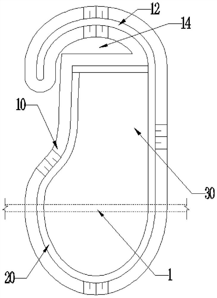
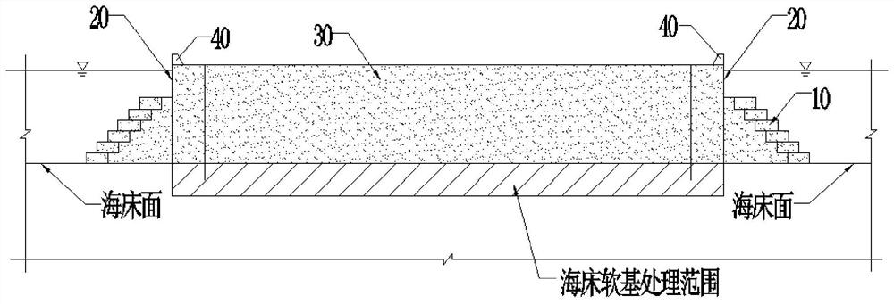
[0030] see first Figure 1 to Figure 5 , the artificial island structure used for the relay extension of the floating tunnel of the present invention has an inverted T-shaped section and includes a lower island base 10 and an upper island body.

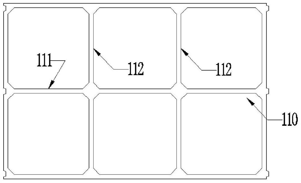
[0031] The plane of the island base 10 is circular, elliptical or diamond-shaped along the water flow with notches to reduce the thrust of the water flow. The island base 10 is divided into an inner part of the island and an outer part of the island; the outer part of the island includes a breakwater 13 and a harbor basin 14 , the gap is the entrance of the harbor basin 14; the island foundation 10 is constructed by multiple layers of backfill sand 12, and each layer of backfill sand 12 is constructed in the cofferdam 11 formed by submerging the super large concrete buoyancy tank 110, and each layer The height of the backfill sand...


PUM


Abstract

The invention discloses an artificial island structure for the relay extension of a floating tunnel, which comprises a lower island base and an upper vertical island body; the island base is constructed of multiple layers of backfill sand, and each layer of backfill sand is made of super large concrete It is built in the cofferdam formed by the submersion of the buoyancy tank, and the outer dimension of each layer of cofferdam gradually decreases upwards, so that the shape of the island base is pyramid-shaped; the upper vertical island body is composed of the island wall and the inner body of the island; the island wall is composed of The steel cylinder grid and the dense packing inside are composed together. The steel cylinder grid is composed of a large steel cylinder main grid and a straight-web steel sheet pile auxiliary grid. The steel large cylinder main grid and the straight-web steel sheet pile All subcells shall be backfilled with sand and compacted, and within 1m from the top of the island wall, gravel cushion and block stone cushion shall be used to protect the surface; the inner body of the island shall be composed of backfilled sand. The artificial island structure of the present invention has the characteristics of self-stability, construction difficulty and relatively small engineering quantity, and can be used for the relay extension of the floating tunnel and the anchorage in the sea of ​​the cable.

Description

technical field [0001] The invention relates to an underwater floating tunnel, in particular to an artificial island structure used for the relay extension of the floating tunnel. Background technique [0002] The submerged floating tunnel, the English name is "Submerged Floating Tunnel", referred to as "SFT". Also known as "Archimedes Bridge" in Italy. The difference between floating tunnels in water and traditional buried tunnels or excavated tunnels is that the floating tunnel structure is surrounded by water, neither on the ground nor through the ground, but mainly depends on the gravity of its own structure, the buoyancy and support of the structure The anchoring force of the system is used to keep it in a fixed position. The suspension tunnel is sealed all around, and this structure has all the characteristics of ordinary tunnels, and should be considered as a "tunnel" rather than a "bridge" from the point of view of use. [0003] Although floating tunnels have cert...

Claims


Application Information

Patent Timeline
Patent Type & Authority Patents(China)
IPC IPC(8): E02D29/067E02B3/18E02B3/06E02B3/10
CPCE02B3/066E02B3/10E02B3/18E02D29/067
Inventor 徐立新郑荣平孙洪春孙旭华敏邱松谢锦波聂亚楠鲁进亮
Owner CCCC THIRD HARBOR ENG
Why Eureka
Try Eureka