Water retaining device

A technology of water retaining device and water stop device, which is applied in water conservancy projects, sea area projects, buildings, etc. It can solve the problems of reduced water stop effect, safety hazards, and aesthetic impact, so as to reduce displacement, reduce the risk of safety hazards, The effect of reducing the water blocking area

Pending Publication Date: 2022-05-13
扬州市格明电子科技有限公司
View PDF1 Cites 0 Cited by
  • Summary
  • Abstract
  • Description
  • Claims
  • Application Information

AI Technical Summary

Problems solved by technology

This technical solution can reduce the height of the pier, but according to the patent drawings, it can be seen that the driving device chamber is located between the two gates, and the door leaf is segmented on the top of the driving device chamber, so that only one end of the door leaf and the rotating shaft is constrained, and the other end is free. , the stressed structure is similar to a cantilever beam, which produces greater deformation in the direction along the river, resulting in a gap between the door leaf and the door leaf, and the water-stop effect is reduced, which not only affects the appearance, but also easily creates safety hazards

Method used


Image

  • Water retaining device
  • Water retaining device
  • Water retaining device

Examples


Embodiment Construction

[0035] In the description of the present invention, it should be understood that the orientation or positional relationship indicated by the terms "below", "outside", "adjacent", "side", etc. are based on the orientation or positional relationship shown in the drawings, and only It is for the convenience of describing the present invention and simplifying the description, but does not indicate or imply that the referred device or element must have a specific orientation, be constructed and operated in a specific orientation, and thus should not be construed as limiting the present invention.

[0036] Furthermore, the terms "first", "second", "third", "fourth", "fifth", etc. are used for descriptive purposes only and are not to be construed as indicating or implying relative importance or implying that The number of technical characteristics.

[0037] In the present invention, unless otherwise clearly specified and limited, the terms "connected", "located", "through", "set", "s...


PUM


Abstract

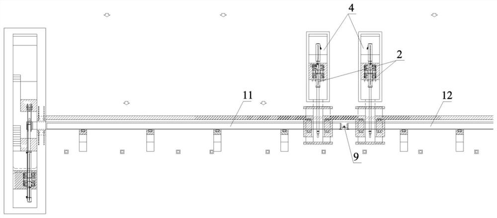
The invention discloses a water retaining device which comprises at least two gate leaves, a driving device, at least two bottom shafts and a river channel driving chamber. The driving device comprises pushing rods and a crank arm which are connected, the crank arm is connected with the bottom shaft, and at least one pushing rod is located below the horizontal plane where the center of the bottom shaft is located. The water retaining device further comprises a first water stopping device, a second water stopping device, a third water stopping device, a fourth water stopping device and a fifth water stopping device. The riverway driving chamber comprises a first side surface and a second side surface; the bottom shaft penetrates through the river channel driving chamber, extends to the outer sides of the first side face and the second side face and is connected with the gate leaf, and the gate leaf is driven to rotate through rotation of the bottom shaft; water stopping between the gate leaves and the river channel driving chamber, between the bottom shafts and the river channel driving chamber, between the adjacent bottom shafts and between the adjacent gate leaves is achieved through the multiple water stopping devices. The gate leaf stress structure is more reasonable, gate leaf stress and displacement are reduced, the height of a river channel driving chamber can be effectively reduced, and the water blocking area of a middle pier is reduced.

Description

technical field [0001] The invention belongs to the field of water conservancy machinery, in particular to a water retaining device. Background technique [0002] When arranging multiple gates in a long-span river, since each gate needs to be equipped with a driving device to drive the opening and closing of the gate, generally a tall pier needs to be arranged between two adjacent gates to accommodate the driving device room to install the driving device, forming a tall gate. The water-blocking section of piers creates obstacles to flood discharge. Chinese invention patent CN210194575U discloses a water retaining device, which includes a gate, a push rod and a crank arm. The push rod is connected to the crank arm. The gate includes a gate rotation shaft and a door leaf. Below the horizontal plane where the center of the rotating shaft of the gate is located, at least one crank arm rotates below the horizontal plane where the center of the rotating shaft of the gate is locat...

Claims


Application Information

Patent Timeline
Patent Type & Authority Applications(China)
IPC IPC(8): E02B7/40E02B7/54
CPCE02B7/40E02B7/54
Inventor 林玉格
Owner 扬州市格明电子科技有限公司
Why Eureka
Try Eureka