Electromagnetic induction cooking utensil

A cooking utensil and electromagnetic technology, applied in the field of kitchen utensils, can solve the problems of limited improvement of thermal energy efficiency utilization rate, limited improvement of thermal energy efficiency utilization rate, and small proportion of thermal radiation, so as to improve recycling "utilization rate, heat The effect of improving energy efficiency utilization and reducing speed

Active Publication Date: 2020-07-10
JOYOUNG CO LTD
View PDF6 Cites 0 Cited by
  • Summary
  • Abstract
  • Description
  • Claims
  • Application Information

AI Technical Summary

Problems solved by technology

However, the efficiency of heat conduction from the bottom of the pan to the panel is relatively high, and the proportion of heat radiation is small at low temperatures. In the prior art, the way that the pan is directly placed on the panel makes the pan directly contact with the panel , the heat transferred from the pan to the panel through heat conduction, the dominant heat transfer method, is far greater than the heat transferred from the panel to the pan through the heat-reflecting layer, so the technical solution of setting the heat-reflecting layer in the prior art can achieve The thermal energy efficiency improvement effect is very limited, and the measured thermal energy efficiency improvement is only 0.1%
The long-term contact between the pan and the panel will scratch the heat reflection layer, and the rough surface of the heat reflection layer will affect the heat reflection effect after the heat reflection layer is damaged
[0005] Moreover, in the prior art, the method for improving energy efficiency of electromagnetic cooking appliances is generally to optimize the coil design, but practice has proved that this type of optimization method is also very limited in improving the utilization rate of thermal energy, and the optimization of the coil is particularly complicated. It requires a lot of cost, even if such an optimized design is carried out at a high cost, the improvement of thermal energy efficiency utilization is only within 1%

Method used


Image

  • Electromagnetic induction cooking utensil
  • Electromagnetic induction cooking utensil
  • Electromagnetic induction cooking utensil

Examples


Embodiment approach 1

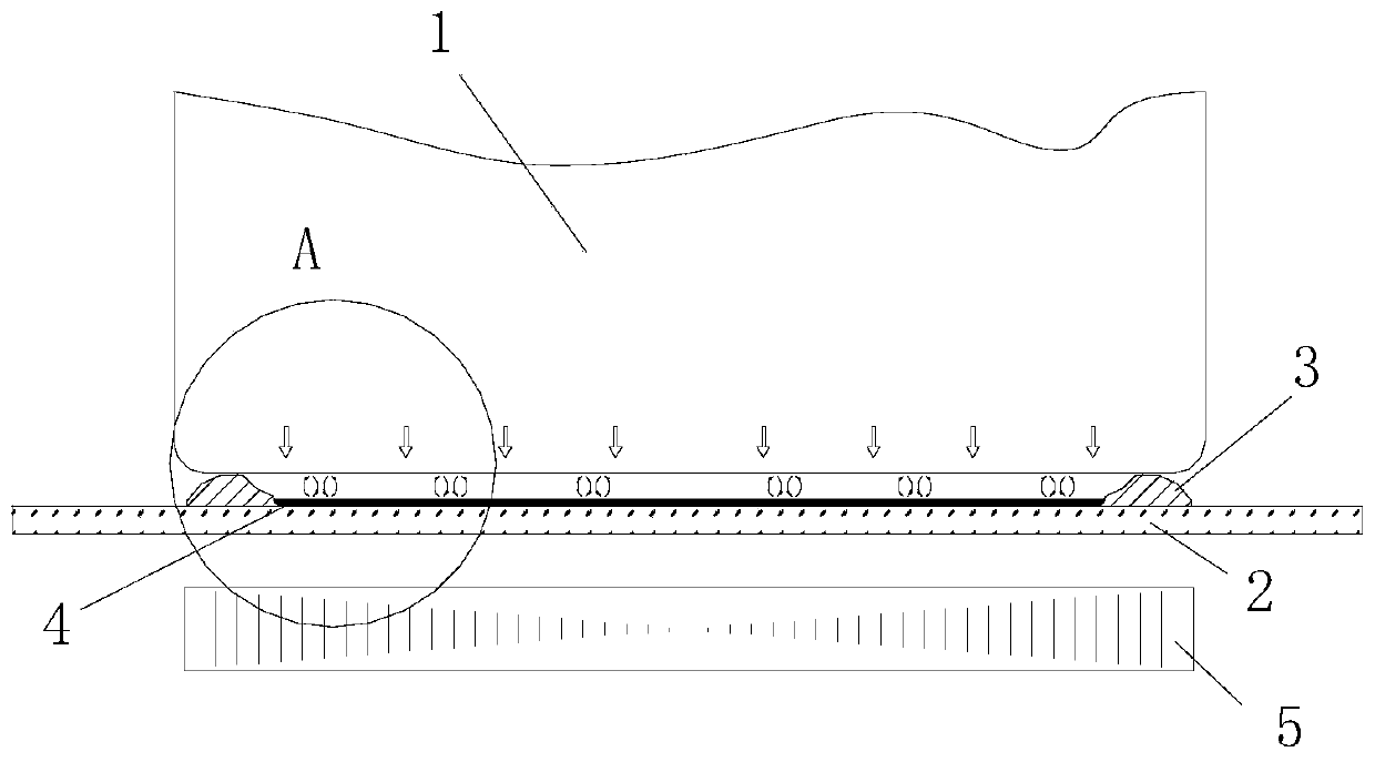
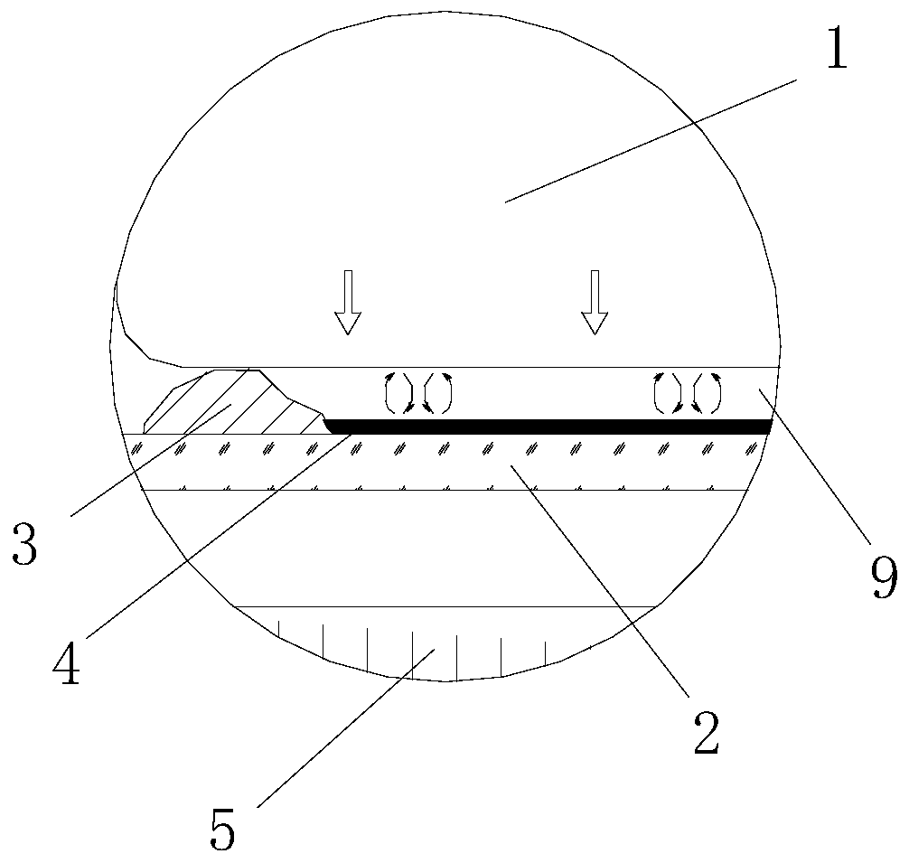
[0054] Such as Figure 1 to Figure 3 As shown, the boss 3 is in a closed ring shape, and the top of the boss 3 has a sealing part, so that the bottom edge of the pot 1 placed on the panel 2 and the boss 3 are sealed and fitted. The lower surface of the boss 3 is sealingly attached to the panel 2 to form a closed air chamber 9 between the panel 2 and the pot 1 . The existence of this closed air chamber isolates the hot air in the closed air chamber 9 from the outside air, so that there is no large-scale convective heat exchange between the inside and outside air, and the rapid loss of a large amount of heat at the bottom of the pot 1 is avoided. This embodiment suppresses heat loss from three levels of "conduction", "radiation" and "heat exchange", greatly reduces heat loss, improves the cooking efficiency of the electromagnetic cooking appliance, and reduces the The heat radiation inside the appliance reduces the temperature rise inside the cooking appliance and protects the ...

Embodiment approach 2

[0060] The structure and principle of this embodiment are basically the same as the first embodiment above, the difference lies in: Figure 4 and Figure 5 As shown, the outer surface of the heating zone is provided with a plurality of said bosses 3, and a plurality of said bosses 3 are arranged at intervals, and among two adjacent bosses 3, the height of the inner boss 31 is lower At the height of the boss 32 located on the outside or flush with each other. In this embodiment, the inner boss 31 can adapt to the pot 11 with a smaller bottom diameter, and the outer boss 32 can adapt to the pot 12 with a larger bottom diameter, thereby enhancing the scope of application of the electromagnetic cooking utensil. . The height setting of the inner and outer bosses avoids the impact on the support of the large-sized pot 1 due to the fact that the inner boss 31 is higher than the outer boss 32 .

[0061] Although a plurality of bosses 3 are provided in this embodiment, the combinati...

Embodiment approach 3

[0063]Same as Embodiment 2, the outer surface of the heating zone in this embodiment is provided with a plurality of bosses 3 arranged at intervals. However, there are obvious differences between this embodiment and the above-mentioned embodiment 1 and embodiment 2 in that: Figure 6 As shown, the plurality of bosses 3 form a non-closed ring structure, that is, in this embodiment, when the pot 1 is placed on the boss 3, the pot 1, the boss 3 and the panel 2 Compared with the above two embodiments, a part of the heat dissipated from the bottom of the pot 1 in this embodiment will pass through the two connected The above-mentioned boss 3 is dissipated to the outside, causing a certain heat loss. Therefore, the thermal energy utilization rate of this embodiment will be reduced to a certain extent compared with the above-mentioned embodiment 1 and embodiment 2, but it has been verified that this embodiment In the process of operation of the electromagnetic cooking utensil in the ...


PUM


Abstract

The invention discloses an electromagnetic induction cooking utensil comprising a base and a panel arranged on the base. The base is internally provided with a heating unit, and the panel is used forbearing a pot. The panel is provided with a heating area corresponding to the position of the heating unit. The outer surface of the heating area is provided with a boss used for supporting the pot. The boss enables a heat insulation gap to exist between the pot placed on the panel and the panel. The outer surface of the heating area is also provided with a heat reflection layer, and the heat reflection layer is used for reflecting heat radiated to the panel. According to the electromagnetic induction cooking utensil, due to the presence of the heat insulation gap, direct heat conduction fromthe pot to the panel is avoided, the heat loss of the pot is lowered, the temperature rise inside the cooking utensil is greatly lowered, and the presence of the heat insulation gap further enhances the heat reflection effect of the heat reflection layer; and the electromagnetic induction cooking utensil blocks heat transfer from the two levels of 'conduction' and 'radiation', which effectively reduces the heat loss of the pot and improves the heating efficiency.

Description

technical field [0001] The application belongs to the technical field of kitchen utensils, in particular to an electromagnetic cooking utensil. Background technique [0002] Induction cooker, induction cooker and other electromagnetic cooking utensils are electric cooking utensils made by the principle of electromagnetic induction heating, which can generate heat directly in the pot without open flame or conduction heating, which is safe and hygienic, and the utilization rate of heating energy efficiency is greatly improved As a result, it is favored by more and more consumers. [0003] The temperature of the cooker during the working process of the electromagnetic cooker is much higher than the temperature of the internal components of the cooker. In the prior art, the cooker is directly placed on the panel of the electromagnetic cooker. During the operation of the electromagnetic cooker, the cooker The heat will be directly transferred to the inside of the cooking applian...

Claims


Application Information

Patent Timeline
Patent Type & Authority Applications(China)
IPC IPC(8): F24C7/08H05B6/12
CPCF24C7/082H05B6/12Y02B40/00
Inventor 朱泽春田海峰
Owner JOYOUNG CO LTD
Why Eureka
Try Eureka