
Throttling control propulsion valve bank

A throttling control and valve group technology, applied in servo motor components, fluid pressure actuating devices, mechanical equipment, etc., can solve the problems of the main valve not working and the valve core not being able to be completely switched, so as to prolong the service life and reduce the pressure. Shock peak, the effect of ensuring stability

Pending Publication Date: 2020-06-23
江苏国瑞液压机械有限公司
View PDF3 Cites 0 Cited by
  • Summary
  • Abstract
  • Description
  • Claims
  • Application Information

AI Technical Summary

Problems solved by technology

[0004] The technical problem to be solved by the present invention is: in view of the tunneling process of the shield machine mentioned in the background technology, the valve core cannot be completely switched sometimes due to the rise of oil temperature, pressure increase and excessive flow of the hydraulic propulsion system during the propulsion process, Technical disadvantage of the problem that makes the main valve inoperable

Method used

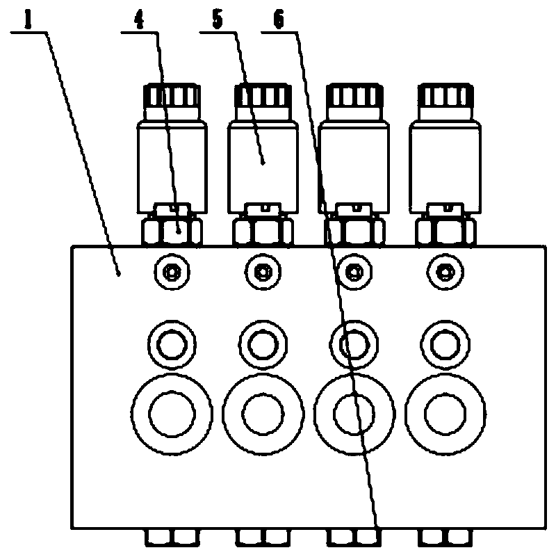
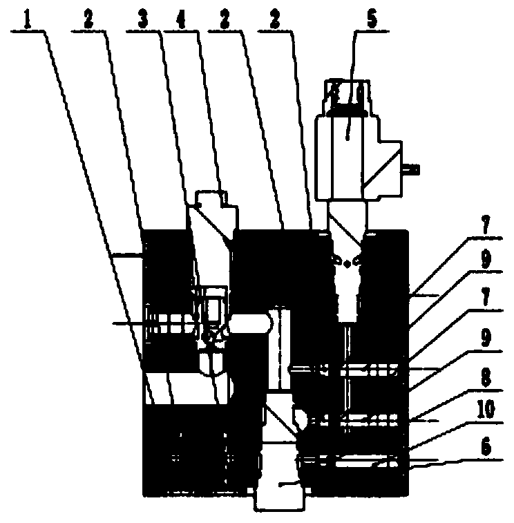
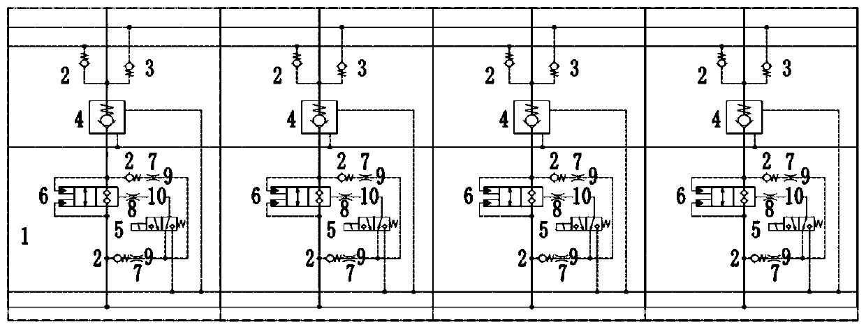

Image

  • Throttling control propulsion valve bank
  • Throttling control propulsion valve bank
  • Throttling control propulsion valve bank

Examples


Embodiment Construction

[0018] When the shield machine is working, the hydraulic system is always in a high-pressure state. With the prolongation of the working time, the temperature of the hydraulic oil gradually increases, resulting in a decrease in the viscosity of the oil, which enters the pilot control oil passage 1 (9 ) gradually increases, when the flow exceeds the working flow of the electromagnetic reversing valve (5), the electromagnetic reversing valve (5) will fail to work, which will affect the work of the pilot control logic valve (6), causing the propulsion system Work is unstable. By adding throttling damper one (7) to each of the two pilot control oil passages one (9), adjust the throttling damper one (7) to control the flow into the electromagnetic reversing valve (5), so that the flow rate is within the rated range , to ensure the stable operation of the pilot control logic valve (6).

[0019] During the switching process of the pilot control logic valve (6), the switching respons...


PUM


Abstract

The invention discloses a throttling control propulsion valve bank which consists of a valve block, a screw-in one-way valve, a screw-in reverse one-way valve, a hydraulic control one-way valve, an electromagnetic reversing valve, a pilot control logic valve, a throttling damper I, a throttling damper II, a pilot control oil channel I, a pilot control oil channel II and the like. The flow enteringa pilot valve and a main valve control cavity is controlled in a multi-time throttling damping mode, so that the working stability of the pilot valve is guaranteed, the function of adjusting the switching and responding time of a main valve element is achieved, the problems that in the hydraulic system propulsion process, due to increasing of oil temperature and increasing of pressure, the flow entering the pilot valve through the one-way valves is overlarge, the work of the valve element cannot be completely switched sometimes, and a main valve cannot work are solved, slow motion of the mainvalve element can be realized by adjusting the throttling damper II, the pressure impact peak value of the system is reduced, the service life of the system is prolonged, stability in the propulsionwork process is ensured, and the function of a shield tunneling machine for controlling propulsion is achieved.

Description

technical field [0001] The invention relates to a hydraulic valve group in a hydraulic propulsion control system, which belongs to the technical field of hydraulic transmission. Background technique [0002] During the tunneling process of the shield machine, the hydraulic system is always in working condition. Long-term work will cause the oil temperature of the hydraulic system to be high; when the hydraulic system is pushing the oil cylinder to work, the hydraulic system is in a state of high load and high pressure. As far as the applicant knows, when the propulsion valve group is working, the system introduces the hydraulic oil to the inlet of the pilot control valve at the maximum flow rate, and sometimes the pilot control valve cannot completely switch the valve core due to excessive flow rate, and the main valve cannot work; When the main valve is opened and closed, a high pressure shock will be generated, which will affect the life of the valve group and the system. ...

Claims


Application Information

Patent Timeline
Patent Type & Authority Applications(China)
IPC IPC(8): F15B13/02
CPCF15B13/027F15B13/02
Inventor 阮瑞勇
Owner 江苏国瑞液压机械有限公司
Learn More