Grinding wheel slotting tool and slotting method

A grooving method and a grinding wheel technology, applied in the field of mechanical processing, can solve the problems of many devices, low processing efficiency, complex structure, etc., and achieve the effects of good grooving quality, solving workpiece burns and thermal deformation, and accurate installation position

Active Publication Date: 2021-09-21
SHANGHAI JIAOTONG UNIV
View PDF15 Cites 0 Cited by
  • Summary
  • Abstract
  • Description
  • Claims
  • Application Information

AI Technical Summary

Problems solved by technology

However, due to the large number of grooves on the grinding wheel, the processing efficiency of the current method of cutting grooves on the grinding wheel with the help of laser is not optimistic.
[0005] Patent document CN208117609U discloses a diamond grinding wheel end face grooving device, including a fixed piece, a fixed block, a first hydraulic cylinder, a moving plate, a second hydraulic cylinder, a mounting plate, a first motor, an annular guide rail, a cutter, and a third hydraulic cylinder , reel, second motor, third motor, fan housing, fan body, dust box, fourth motor and connecting rod, use the different lifting heights of the four second hydraulic cylinders to adjust the inclination angle of the moving plate , so as to adjust the inclination angle of the diamond grinding wheel, use the second motor to drive the rotating shaft of the reel to rewind the steel wire cable, thereby controlling the rise of the fan housing, moving the material guide pipe out of the dust box, and removing the dust inside the dust box The waste is disposed of, but the device has a lot of equipment and a complicated structure

Method used


Image

  • Grinding wheel slotting tool and slotting method
  • Grinding wheel slotting tool and slotting method
  • Grinding wheel slotting tool and slotting method

Examples


Embodiment Construction

[0040] The present invention will be described in detail below in conjunction with specific embodiments. The following examples will help those skilled in the art to further understand the present invention, but do not limit the present invention in any form. It should be noted that those skilled in the art can make several changes and improvements without departing from the concept of the present invention. These all belong to the protection scope of the present invention.

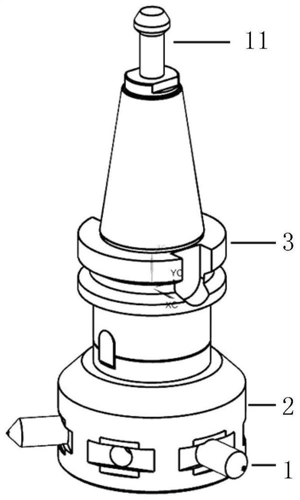
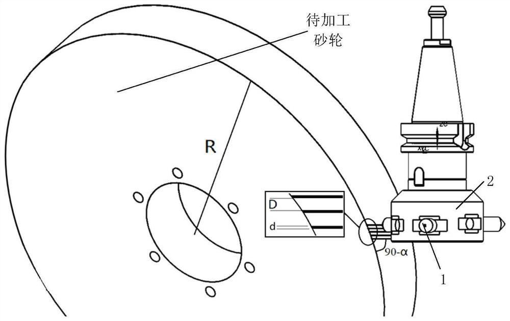
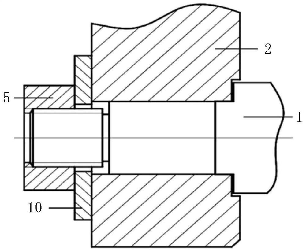
[0041] The invention provides a grinding wheel grooving tool, such as figure 1 , figure 2 As shown, it includes a grinding wheel dresser 1, a connecting block 2 and a disc milling cutter holder 3; the disc milling cutter holder 3 is installed on the connecting block 2; Circumferential arrangement.

[0042] The present invention relies on the grinding wheel dresser 1 to relatively move in the grinding wheel grinding area and cut the grinding wheel to form a meshing of the circumferential surface struc...


PUM


Abstract

The invention provides a grinding wheel grooving tool and a grooving method, belonging to the field of mechanical processing, comprising a grinding wheel dresser, a connecting block and a disc milling cutter holder; the disc milling cutter holder is installed on the connecting block and along the With the circumferential arrangement of the connecting blocks, the grinding wheel dresser forms a spiral installation track along the connecting circumferential direction, and the orientation of the grinding wheel dresser is perpendicular to the tangential direction of the spiral track. The present invention relies on the grinding wheel dresser to move relatively in the grinding wheel grinding area and cut the grinding wheel to form a meshing of the circumferential surface structure of the grinding wheel. The grinding wheel dresser and the grinding wheel to be processed can each rotate around the axis and perform mutual meshing worm gear movement. The overlapping part of the grinding wheel dresser and the grinding wheel to be processed, the grinding wheel quick slotting tool cuts the grinding wheel to complete the slotting operation, realizes slotting on the grinding wheel and makes the grinding wheel circumferentially form grid grooves, and solves the problem of grinding in the prior art. The defects of workpiece burns and thermal deformation caused by cutting, good grooving quality and high efficiency.

Description

technical field [0001] The invention relates to the field of machining, in particular to a grinding wheel grooving tool and a grooving method. Background technique [0002] Grinding is a cutting process in which the surface of a workpiece is machined with abrasive tools such as a high-speed rotating grinding wheel. It is a processing method commonly used in mechanical processing and has a very important position. Grinding is used to process special and complex shaped surfaces such as internal and external cylindrical surfaces, conical surfaces, planes, threads, gears and splines of various workpieces. Due to the high hardness of the abrasive grains and the self-sharpening of the abrasive tool, grinding can be used to process various materials, including hardened steel, high-strength alloy steel, hard alloy, glass, ceramics and marble and other high-hardness metals and non-metallic materials. metallic material. [0003] Grinding is mainly used for finishing, removing workp...

Claims


Application Information

Patent Timeline
Patent Type & Authority Patents(China)
IPC IPC(8): B24B53/06B23K26/38B23K26/70
CPCB23K26/38B24B53/062B23K26/70
Inventor 姚振强宋嘉诚沈洪
Owner SHANGHAI JIAOTONG UNIV
Why Eureka
Try Eureka