Eureka AIR delivers breakthrough ideas for toughest innovation challenges, trusted by R&D personnel around the world.

Circlip for cylindrical roller bearing and its production method

A technology for cylindrical roller bearings and circlips, which is applied to bearing components, shafts and bearings, mechanical equipment, etc., and can solve the problems of loose dimensions and tolerances of circlips, difficult control of main dimensions and tolerances, winding of spring steel strips and Lock complex problems to achieve the effect of solving burn problems, simple manufacturing process and long service life

Inactive Publication Date: 2009-02-18
SHIBIAI SPECIAL BEARING LUOYANG
View PDF8 Cites 0 Cited by
  • Summary
  • Abstract
  • Description
  • Claims
  • Application Information

AI Technical Summary

Problems solved by technology

However, because the main dimensions and tolerances of the retaining ring are not strict, the manufacturing process is more complicated. For example, the opening is processed before heat treatment, and the size of the incision is controlled by mechanical means, and then heat treatment is performed, so the main dimensions and tolerances are not easy to control.
For another example, in order to ensure the elasticity of the retaining ring, the size of the notch must be guaranteed, and the guarantee of the notch size is controlled by the tightness of the bundled spring steel belt, so that the winding and locking of the spring steel belt is more complicated, and because of The thickness of the steel strip is thin, and the reliability of spot welding is poor

Method used


Image

  • Circlip for cylindrical roller bearing and its production method
  • Circlip for cylindrical roller bearing and its production method
  • Circlip for cylindrical roller bearing and its production method

Examples


Embodiment Construction

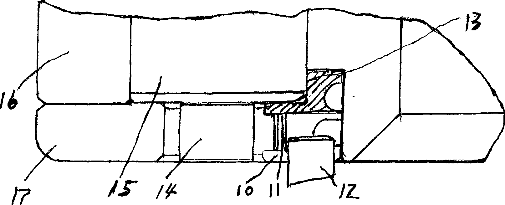
[0034] Depend on Figure 4 , Figure 5 It can be seen that the elastic circlip is connected in a way of butting two ends, and an opening 18 is provided on the lower end surface 25 of the connecting end, and an oblique cut 19 is arranged on the upper end surface of the connecting end, and the slope of the oblique incision is 45°. The inner ring of the ring is provided with two oil seal grooves 22, and the oil seal grooves 22 extend outward from the opening 18 with a depth gradually becoming shallower. The small outer diameter of the retaining ring is the raceway surface 13, and the large outer diameter is the fixed spring steel sheet 23. The fixed groove 11 of the spring steel sheet, the spring steel sheet 23 is arranged in the fixed groove 11 of the spring steel sheet with each 30 ° of circumference around the center line of the circlip opening 18. The spring steel sheet 23 of the circlip of the present invention is made up of two steel sheets of 0.5mm, and the spring steel s...


PUM


Abstract

A circlip is used in a cylindrical roller bearing. Two ends of the circlip are connected via two spring steel pieces. An opening is arranged on the lower end surface of the connecting end, while an oblique notch connected with the opening is arranged on the upper end surface of the connecting end. An internal ring of the circlip is equipped with two oil-seal grooves, which extend outwards from the left and the right of the opening and become shadow gradually. The external ring of the circlip is equipped with a raceway surface to give load to a roller, and a fixing groove to fix the spring steel pieces. The spring steel pieces are arranged in the fixing groove at an angle of 30 degrees with both sides of the central line of the circlip opening in a perimetric way. As two ends of the opening are fixed with the spring steel pieces due to the size of the opening, the circlip of the invention is provided with the inward elasticity to give load to the roller and press the roller to the raceway in the external ring. When the external ring of the bearing revolves, the roller is forced to rotate. As the circlip cannot rotate with the bearing, the roller will not slide so as to solve the problem of burning of the roller. The invention is simple in the process. The circlip is provided with the good elasticity, the long usable life and the low cost, can greatly promote the working efficiency.

Description

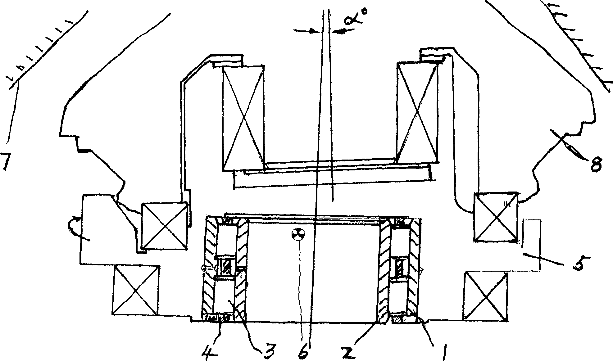
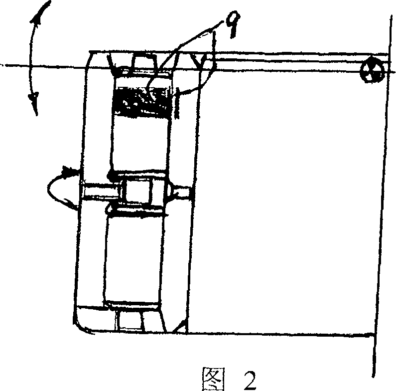
technical field [0001] The invention relates to a cylindrical roller bearing used in a cone crusher, in particular to a circlip used on the cylindrical roller bearing and a manufacturing method thereof. Background technique [0002] The cone crusher is composed of an outer cone (a non-moving shell) and a rollable inner cone. The size of the opening between the inner and outer cones can be adjusted. The rollable inner cone is mounted on an eccentric seat to realize swinging motion. Broken at the opening, the material is discharged at the opening. Depend on figure 1 shown. [0003] A cylindrical roller bearing is installed under the eccentric seat, and the eccentric seat rotates and swings to make the bearing bear the eccentric load. After 15 minutes of operation, the upper part of the inner ring raceway and the contacting roller surface are severely burned, which makes the bearing invalid. Shown in Figure 2. [0004] The above phenomenon is explained as that there is no r...

Claims


Application Information

Patent Timeline
Patent Type & Authority Patents(China)
IPC IPC(8): F16C33/34
Inventor 单宝林梅建洛王迪
Owner SHIBIAI SPECIAL BEARING LUOYANG
Why Eureka
Eureka Blog
Learn More