Hydraulic radiating system, hydraulic system of riser suspension device and radiating method

A heat dissipation system and hydraulic technology, applied in the direction of fluid pressure actuation device, fluid pressure actuation system components, servo motors, etc., can solve the problems of difficult operation, inability to arrange, high price, etc., to reduce volume and cost, heat dissipation good effect

Active Publication Date: 2020-06-05
CHINA NAT OFFSHORE OIL CORP +1
View PDF11 Cites 3 Cited by
  • Summary
  • Abstract
  • Description
  • Claims
  • Application Information

AI Technical Summary

Problems solved by technology

There are certain problems in the field application of these two suspension methods: when the rigid suspension is adopted, the riser string is rigidly connected to the platform, and the acceleration of the platform motion is directly transmitted to the riser string, which may cause dynamic compression of the riser, resulting in buckling failure of the riser. It may also cause the tension at the top of the riser to be much greater than the wet weight of the riser (indicating the weight of the riser with buoyancy blocks in the water, that is, the dry weight minus the buoyancy), causing the riser to break and fall into the sea; The dynamic load of the water pipe due to the heave movement of the platform is significantly reduced, and the safety of the riser suspension is improved. However, it is very difficult to take the riser on site and connect the riser back, and if several risers are not taken out, the riser chain risk of bottoming out
If a high-pressure heat dissipation system is used, it is generally a tubular radiator, which is huge in size and expensive, and cannot be arranged on site. Therefore, the use of a reasonable heat dissipation system becomes the key to the successful application of the riser suspension device in the field.

Method used


Image

  • Hydraulic radiating system, hydraulic system of riser suspension device and radiating method
  • Hydraulic radiating system, hydraulic system of riser suspension device and radiating method
  • Hydraulic radiating system, hydraulic system of riser suspension device and radiating method

Examples


Embodiment approach

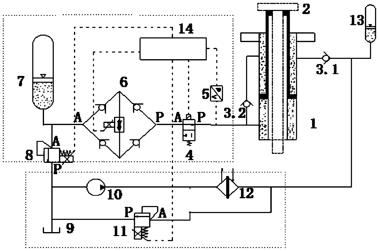
[0034] According to an embodiment of the present invention, the low-pressure circuit further includes a low-pressure relief valve 11 and a fuel tank 9, the fuel tank 9 and the high-pressure relief valve 8, the hydraulic pump 10, and the low-pressure relief valve 11 Both are connected, and the low-pressure relief valve 11 is connected with the low-pressure accumulator 13 and the second one-way valve 3.1.

[0035] According to an embodiment of the present invention, the oil tank 9 is connected in series with the low pressure relief valve 11, the hydraulic pump 10 and the cooler 12 are connected in series, and the oil tank 9 is connected with the low pressure relief valve 11 in series. The connecting line is connected in parallel with the line connecting the hydraulic pump 10 and the cooler 12.

[0036] According to an embodiment of the present invention, the high-pressure circuit further includes a shut-off valve 4, one end of the shut-off valve 4 is connected to the throttle block 6...


PUM


Abstract

The invention relates to a hydraulic radiating system, a hydraulic system of a riser suspension device and a radiating method. The hydraulic radiating system comprises a high-pressure loop and a low-pressure loop, wherein the high-pressure loop and the low-pressure loop are respectively connected with a differential hydraulic cylinder, the high-pressure loop comprises a high-pressure energy accumulator, a throttle valve block, a high-pressure overflow valve and a first one-way valve; the first one-way valve is connected with the rod cavity of the differential hydraulic cylinder and connected with rodless cavities of the throttle valve block and the differential hydraulic cylinder, and the other end of the throttle valve block is connected with the high-pressure energy accumulator and the high-pressure overflow valve; the low-pressure loop comprises a low-pressure energy accumulator, a cooler, a hydraulic pump and a second one-way valve, the second one-way valve is connected with the rod cavity of the differential hydraulic cylinder and connected with the low-pressure energy accumulator and the cooler, and the cooler is connected with the hydraulic pump, which is connected with thehigh-pressure overflow valve. According to the invention, the cooling hydraulic oil of the low-pressure loop can enter the hydraulic cylinder and mix with the high-temperature hydraulic oil of the high-pressure loop, and the temperature of the hydraulic oil of the high-pressure loop is reduced.

Description

Technical field [0001] The invention relates to the technical field of hydraulics, in particular to a hydraulic heat dissipation system, a hydraulic system of a riser suspension device and a heat dissipation method. Background technique [0002] When encountering extreme weather such as typhoons, ocean floating drilling platforms sometimes cannot stay in place. If the typhoon path can be accurately predicted in advance, it is generally chosen to disconnect the riser from the LMRP (lower riser assembly) and recover the upper deck, and then drive the drilling platform to a safe area. In the ultra-deep waters, it will take several days to reconnect and release the riser after the typhoon. At the same time, recycling or decentralization must be carried out under better environmental conditions. In order to reduce downtime and reduce operational risks in harsh environments, suspending all or part of the riser on the drilling platform and then evacuating it is the current common meth...

Claims


Application Information

Patent Timeline
Patent Type & Authority Applications(China)
IPC IPC(8): F15B11/08F15B13/02F15B1/02F15B15/17F15B21/0423
CPCF15B11/08F15B13/027F15B13/02F15B1/02F15B15/17F15B21/0423
Inventor 刘健许亮斌盛磊祥刘书杰王宇肖凯文郝希宁李朝玮
Owner CHINA NAT OFFSHORE OIL CORP
Why Eureka
Try Eureka