Eureka AIR delivers breakthrough ideas for toughest innovation challenges, trusted by R&D personnel around the world.

Medical connecting device

A connecting device and remote technology, applied in the field of medical devices, can solve the problems of single performance of the connecting pipe, inability to realize the function of liquid passing, and lack of versatility, etc.

Pending Publication Date: 2020-05-29
MICRO TECH (NANJING) CO LTD
View PDF0 Cites 12 Cited by
  • Summary
  • Abstract
  • Description
  • Claims
  • Application Information

AI Technical Summary

Problems solved by technology

For complex operations such as endoscopic surgery, a product that integrates marking, flushing, injection, cutting, coagulation, etc. is required. Therefore, the functional requirements of the connecting tube for this product are relatively high, otherwise frequent Replacement of instruments, prolonging operation time
[0005] However, the performance of the traditional connecting tube for endoscope accessories is relatively single, and it can only realize part of the functions, and it is not universal. For example, the connecting tube for injection needles is generally made of polymer materials, which can realize the function of passing liquid, but cannot realize the function of conducting electricity. For example, the connecting tube for high-frequency incision knife, some of which use stainless steel tube, although it realizes the function of conducting liquid, but the overall structure is consistent, the front end is hard, and it is difficult to pass through the bend of the endoscope; such as the connecting tube for hemostat, it is generally used Solid stainless steel wire or stainless steel wire rope can only realize the function of conducting electricity, but not the function of passing liquid; such as the existing coated spring tube, which is generally made of spring wire, the whole product is consistent in front and back, and flexibility and rigidity cannot coexist.

Method used


Image

  • Medical connecting device
  • Medical connecting device
  • Medical connecting device

Examples


Embodiment 1

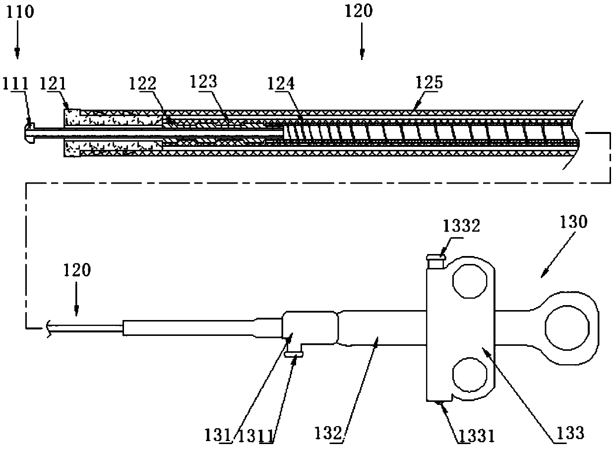
[0026] Such as figure 2 It is a schematic diagram of applying the device of the present invention to a high-frequency incision knife. The high-frequency incision knife includes an electrode part 110 , a transport part 120 and an operation part 130 . Wherein, the electrode 111 includes a hollow tubular portion and a protrusion. The shape of the electrode is not limited to this structure, and it can also be other structures that include a hollow tubular portion. The hollow tubular portion of the electrode can pass through liquid, pass through powder, cut, etc.; limiter 121 At the same time, it plays the role of insulation. The limiter 121 adopts a tubular structure, made of heat-resistant and insulating materials such as zirconia, and is fixedly connected with the distal end of the outer tube 125 to limit the extension of the distal end of the electrode 111. and retract, and the size of its inner hole is larger than the outer diameter of the hollow tubular part of the electrod...

Embodiment 2

[0029] Such as image 3 It is a schematic diagram of the device of the present invention applied to ultrasonic aspiration biopsy needles. The ultrasonic suction biopsy needle includes a puncturing part 210 , a conveying part 220 and an operating part 230 . Among them, 211 is a puncture needle, which adopts a hollow tubular structure and includes a needle point for puncture sampling; 221 is a sealing member, whose non-planar structure is conducive to sealing, and is fixedly connected with the puncture needle 211; the insulating layer 222 covers the sealing member 221 and the spiral The surface of the tube 223 acts as a seal; the outer tube 224 extends from the proximal end to the distal end to support the internal connection device, and is convenient for pushing the puncture needle 211; the core rod 231 is connected with the proximal end of the outer tube 224, and the slider 232 can move along the The rod 231 moves, and the slider 232 includes a Luer connector 2321 . The heli...

Embodiment 3

[0032] Such as Figure 4 It is a schematic diagram of applying the device of the present invention to a hemostatic forceps. The hemostatic forceps includes a clamping part 310 , a delivery part 320 and an operating part 330 . Wherein, 311 is the forceps head, and its shape is not limited to this structure, also can be as scissors shape, sawtooth shape, is used for electrocoagulation hemostasis or cutting, is movable and is connected with fixed seat 312; Fixed seat 312 adopts the material that has conductivity It is used to support the clamp head 311, and can make the clamp head 311 open and close smoothly, and its inner hole size is larger than the outer diameter of the pull rod 313; the seal 321 is made of conductive material, and the non-planar structure is conducive to sealing , the proximal end of the sealing member 321 is connected with the fixed seat 312; 322 is an insulating layer, which is made of insulating materials such as PTFE, and covers the surface of the sealin...


PUM


Abstract

The invention discloses a medical connecting device. The medical connecting device has a near end and a far end and comprises an insulating layer and a spiral tube, wherein the insulating layer coversthe outermost layer of the whole device; the spiral tube is of a conductive hollow tubular structure and has a spiral structure; and the spiral structure has a screw pitch gradually changing from thenear end to the far end. According to the medical connecting device, the functions of electric conduction, liquid passing, powder spraying, negative pressure suction, sealing, insulation, supportingand the like can be integrated.

Description

technical field [0001] The invention relates to a medical connecting device in the field of medical devices, in particular to a device for an endoscope accessory integrating the functions of conduction, liquid flow, powder spraying, negative pressure suction, sealing, insulation, support and the like. Background technique [0002] Endoscopic technology has been born for more than 50 years. It has gone through the stages from disease diagnosis to disease treatment. It has been very effective and reliable for the treatment of some digestive diseases, and has even become the first choice for treatment. In recent years, with the development of endoscopic technology, endoscopic tissue biopsy, endoscopic mucosal resection (Endoscopic mucosal resection, EMR) and endoscopic submucosal dissection (Endoscopic submucosal dissection, ESD) have been widely used. The treatment of tract bleeding, polypectomy and early cancer is gradually becoming the first choice of treatment. Among them,...

Claims


Application Information

Patent Timeline
Patent Type & Authority Applications(China)
IPC IPC(8): A61B1/00A61B10/04A61B18/14
CPCA61B1/00119A61B1/00128A61B1/00137A61B18/1492A61B18/1445A61B10/04A61B2010/045A61B2018/00589A61B10/0283A61B18/1442A61B2018/146A61B2018/1457A61B2018/144A61B2018/1417A61B2018/00601A61B2018/00083A61B18/12A61B90/08A61B17/34A61B1/012A61B18/1482A61B1/00087A61B2018/00172
Inventor 唐志范茗侨解欢沙德青李常青冷德嵘刘春俊
Owner MICRO TECH (NANJING) CO LTD
Why Eureka
Eureka Blog
Learn More