PMI foam loop radome

A loop antenna and foam technology, applied in the field of structural parts, can solve the problems of PMI foam radome compounding, etc., and achieve the effects of good shock absorption, high elastic modulus, and high tensile strength

Active Publication Date: 2020-05-22
10TH RES INST OF CETC
View PDF10 Cites 0 Cited by
  • Summary
  • Abstract
  • Description
  • Claims
  • Application Information

AI Technical Summary

Problems solved by technology

However, for antennas with frequency selective filtering requirements, PMI foam radome cannot be directly compounded with filter network lik...

Method used


Image

  • PMI foam loop radome
  • PMI foam loop radome
  • PMI foam loop radome

Examples


Embodiment Construction

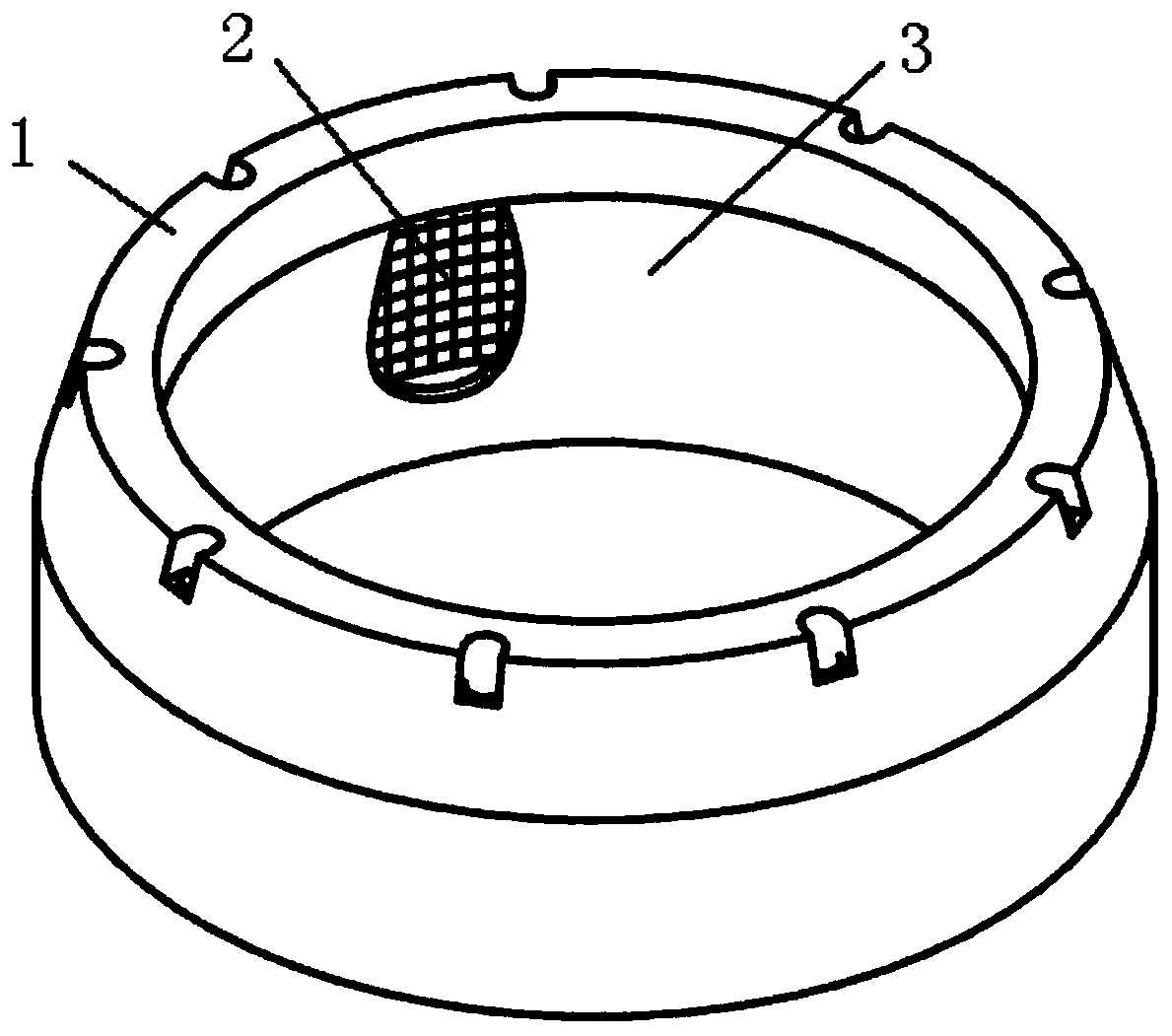
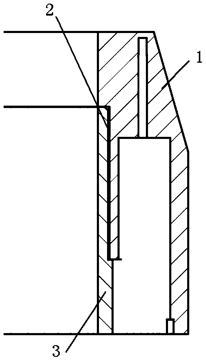
[0023] read figure 1 , figure 2 . In the preferred embodiment described below, a PMI foam ring radome includes: a hollow column cone ring radome shell with uniform and isotropic PMI foam as the main material, characterized in that the ring radome The appearance is a cylindrical cylinder with chamfered corners. There is a cavity for placing the antenna unit inside the cylinder. The frequency selective surface of the periodic array structure composed of passive resonant units is embedded in the inner wall of the cylinder. The frequency selective surface forms a space The filter surrounds the inner wall of the annular cylinder to form a flexible microstrip filter network 2; when the incident electromagnetic wave passes through the filter network, the force generated by the electric field on the electrons causes it to oscillate, thereby forming an induction on the metal surface of the filter network Current, a part of the energy of the incident electromagnetic wave is converted...


PUM


Abstract

The invention discloses a PMI foam loop radome, and aims to provide an antenna which is high in transmission efficiency, small in transmission loss, light in weight and good in damping performance andhas a filtering function. The method is realized through the following technical scheme: the appearance of the annular radome is a cylinder with chamfers, a cavity used for containing antenna units is formed in the cylinder, passive resonance units are embedded into the cylinder wall to form a frequency selection surface of a periodic array structure, a spatial filter is formed, and the filter surrounds the annular cylinder wall to form a flexible microstrip filter network; when incident electromagnetic waves pass through the filter network, acting force generated by the electric field on electrons enables the electrons to oscillate, so that an induction current is formed at the metal surface of the filter network, part of the energy of incident electromagnetic waves is converted into kinetic energy for maintaining an electronic oscillation state, and the other part of energy passes through the frequency selection surface to be transmitted to the antenna unit. The PMI foam loop radomecarries the filter network to selectively filter the electromagnetic waves of the non-antenna working frequency bands.

Description

technical field [0001] The invention relates to a structure for protecting an antenna system from the external environment, in particular a rigid radome with filtering properties. Background technique [0002] The radome is a shell-shaped multifunctional wave-transparent structure used to protect the antenna system. Its mechanical properties can prevent the antenna system from being damaged in various harsh environments such as wind, rain, snow, sand, solar radiation, and pneumatic heating. Its electrical performance has good electromagnetic wave penetration characteristics, especially the wave transparency and filtering ability of the electromagnetic wave in the working frequency band of the antenna is directly related to the quality of the antenna performance index. [0003] At present, most radomes are in the form of antenna system protective shells, and the inner space is used to place the functional components of the antenna. Since the radome is an obstacle in front of...

Claims


Application Information

Patent Timeline
IPC IPC(8): H01Q1/42
CPCH01Q1/42
Inventor 李响谢义水段恒毅郑雪晓
Owner 10TH RES INST OF CETC
Why Eureka
Try Eureka