LD light-emitting device and preparation method thereof

A light-emitting device and light beam technology, applied in the field of optical components, can solve problems such as failure of fluorescent materials

Pending Publication Date: 2020-05-19
SONGSHAN LAKE MATERIALS LAB +1
View PDF0 Cites 1 Cited by
  • Summary
  • Abstract
  • Description
  • Claims
  • Application Information

AI Technical Summary

Problems solved by technology

[0003] The purpose of the embodiment of the present application is to provide an LD light-emitting device and its preparation method...

Method used


Image

  • LD light-emitting device and preparation method thereof
  • LD light-emitting device and preparation method thereof
  • LD light-emitting device and preparation method thereof

Examples


Embodiment Construction

[0034] In order to make the purposes, technical solutions and advantages of the embodiments of the present application clearer, the technical solutions in the embodiments of the present application will be clearly and completely described below in conjunction with the drawings in the embodiments of the present application. Obviously, the described embodiments It is a part of the embodiments of this application, not all of them. The components of the embodiments of the application generally described and illustrated in the figures herein may be arranged and designed in a variety of different configurations.

[0035] Accordingly, the following detailed description of the embodiments of the application provided in the accompanying drawings is not intended to limit the scope of the claimed application, but merely represents selected embodiments of the application. Based on the embodiments in this application, all other embodiments obtained by persons of ordinary skill in the art w...


PUM

PropertyMeasurementUnit
Angleaaaaaaaaaa

Abstract

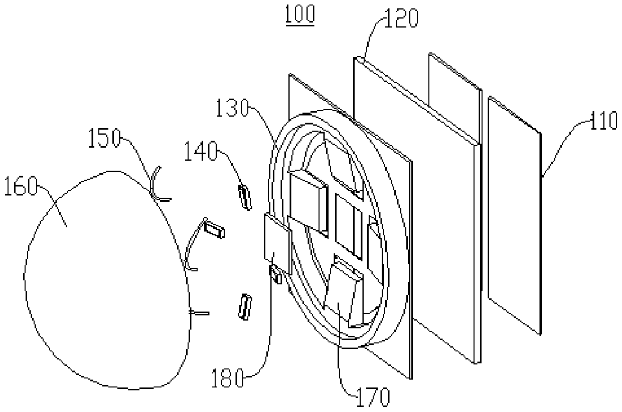
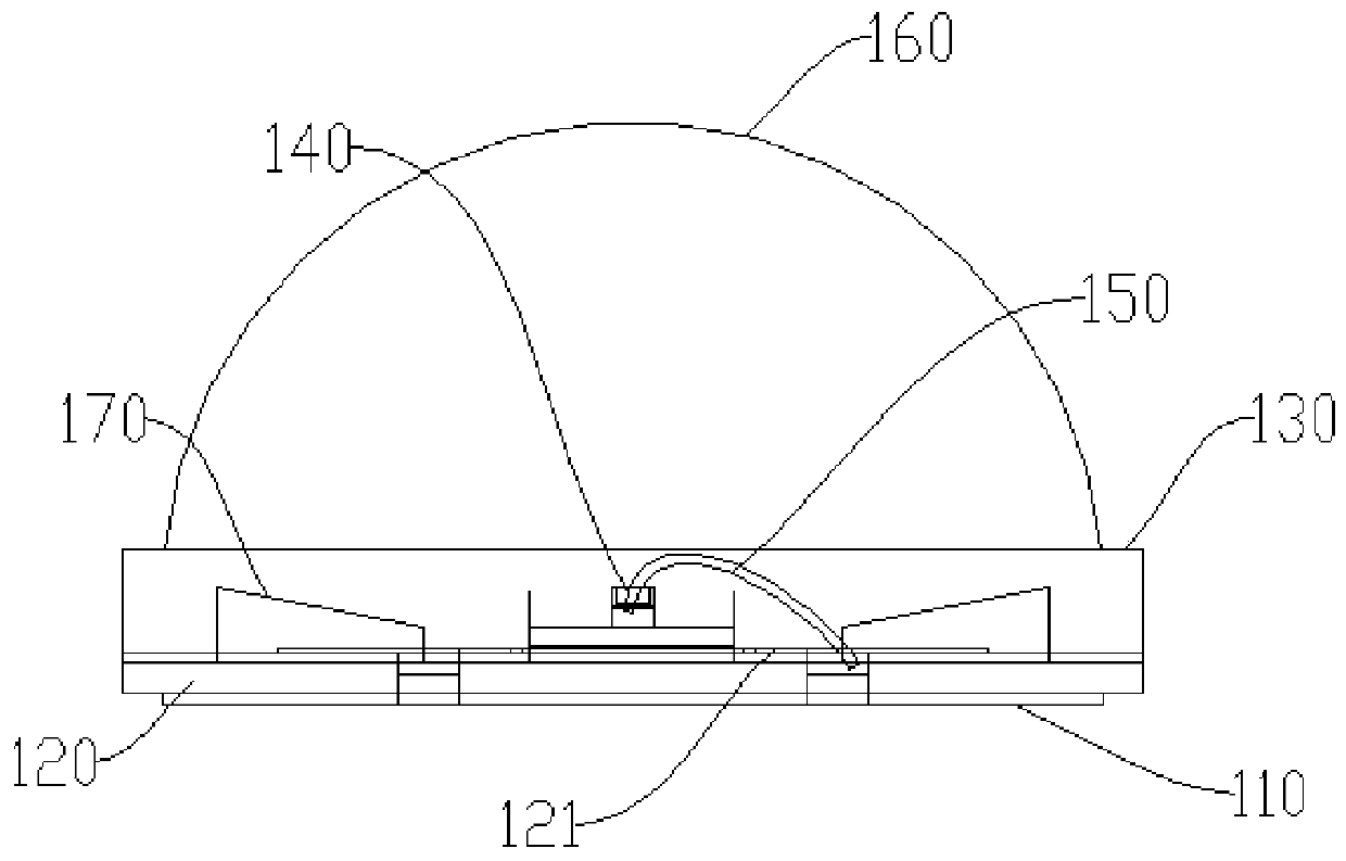
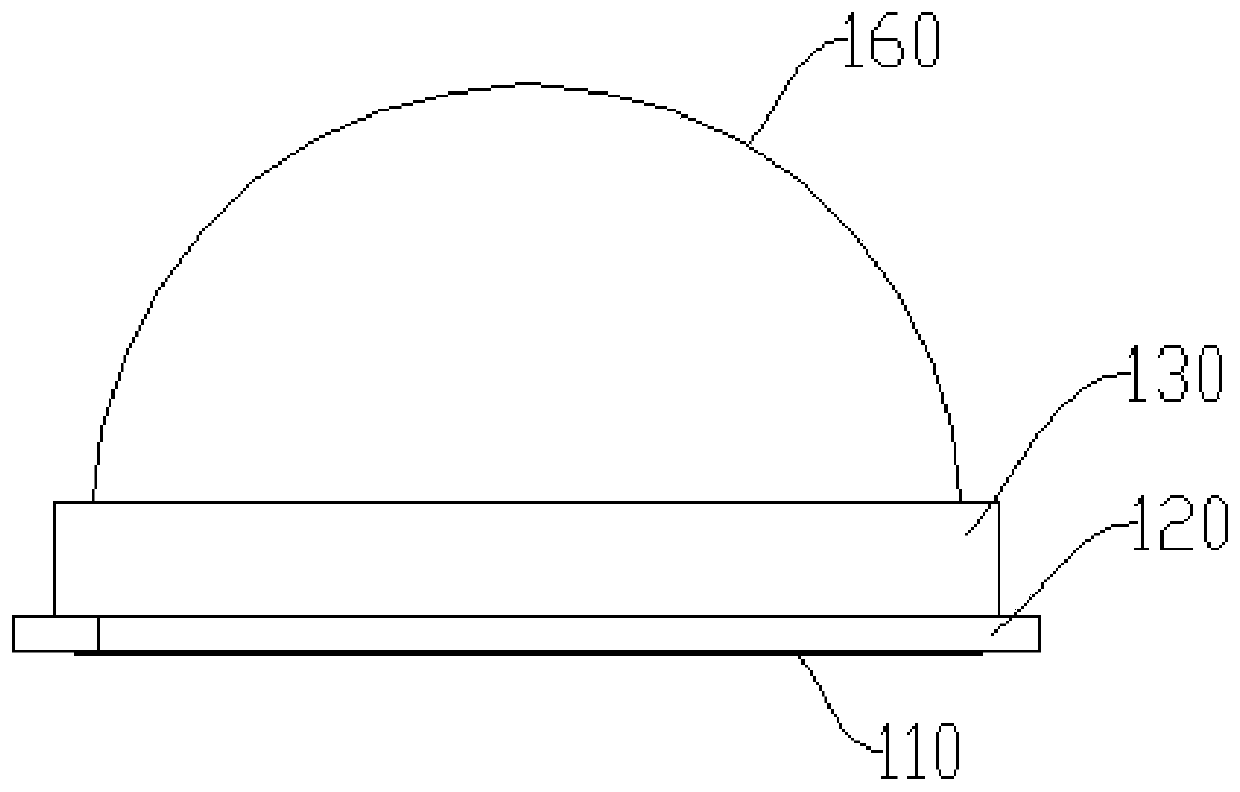
The invention relates to the field of optical elements, in particular to an LD light-emitting device and a preparation method thereof. The LD light-emitting device comprises a substrate, a fluorescentlayer, a heat sink, an LD chip and an optical lens. The backlight surface of the fluorescent layer is attached to the substrate; the LD chip is mounted on the heat sink, and at least part of light beams emitted by the LD chip can irradiate the reflective surface of the fluorescent layer; the optical lens is connected with the substrate. The whole backlight surface of the fluorescent layer can conduct heat through the substrate, the direct contact area of the fluorescent layer and the substrate is increased, and the heat transfer efficiency is improved. The heat of the fluorescent layer is quickly dissipated through the substrate; light of the LD chip can only irradiate the reflective surface of the fluorescent layer, so that heat conducted to the fluorescent layer by the LD chip is reduced, and the heat dissipation problem of the fluorescent layer is improved to a great extent. The situation that the fluorescent layer fails due to poor heat dissipation is effectively improved, and theproblem of light attenuation or color drift of the LD light-emitting device is further solved

Description

technical field [0001] The present application relates to the field of optical elements, in particular to an LD light-emitting device and a preparation method thereof. Background technique [0002] At present, the light-emitting devices of laser diodes usually use fluorescent functional materials to convert monochromatic laser light into white light; fluorescent materials have low thermal conductivity and poor thermal stability, and the blue laser emitted by laser diodes is likely to cause thermal quenching failure of fluorescent materials. Cause problems such as light fading or color drift. Contents of the invention [0003] The purpose of the embodiments of the present application is to provide an LD light-emitting device and a manufacturing method thereof, which aims to improve the problem that the laser light emitted by the existing LD chip easily causes the failure of the fluorescent material. [0004] The first aspect of the present application provides an LD light ...

Claims


Application Information

Patent Timeline
IPC IPC(8): H01S5/022H01S5/024H01S5/028
CPCH01S5/02438H01S5/028H01S5/023H01S5/0233H01S5/0235H01S5/02355
Inventor 申小飞曹永革李英魁麻朝阳文子诚王恩哥王充
Owner SONGSHAN LAKE MATERIALS LAB
Why Eureka
Try Eureka