Satellite-borne SAR dual-polarized microstrip radiation sub-array antenna

A dual-polarization, microstrip technology, applied in the direction of antenna, antenna array, radiating element structure, etc., can solve the design, engineering design and preparation scheme that the cross-polarization and isolation of a single radiating sub-array are not optimal. Verification, unsuitability for large-scale engineering applications, etc., to achieve good cross-polarization performance, avoid vacuum blasting, and small deformation effects

Active Publication Date: 2020-05-19
CHINA ELECTRONICS TECH GRP CORP NO 14 RES INST
View PDF10 Cites 8 Cited by
  • Summary
  • Abstract
  • Description
  • Claims
  • Application Information

AI Technical Summary

Problems solved by technology

[0003] There are many designs and studies on dual-polarized microstrip antennas at home and abroad, and its theory is relatively mature. It has been studied and analyzed in detail from the aspects of unit selection, linear array and area array design, and low cross-polarization. A 1× Three types of dual-polarized microstrip sub-arrays in the form of 8-unit double-slit coupling feeding and two types of 1×16-unit hybrid feeding. Its thickness is relatively large, and the design of the radio frequency interface is complex, which is not suitable for mass engineering applications, and the feeder between the two polarizations does not adopt corresponding isolation measures, and the feeder has its own radiation effect, resulting in cross-polarization and The isolation has not reached the optimal design. The design of the radiation sub-array uses foam as the supporting material between the layers of the microstrip antenna. Therefore, there is still a certain gap in the design and research of spaceborne dual-polarized microstrip antennas for engineering applications.
[0004] The currently operating SAR satellites using microstrip radiation sub-arrays are the COSMO satellite developed by Italy and the ALOS satellite developed by Japan respectively, but there is little information about their radiation sub-arrays, and the specific engineering design and preparation scheme cannot be verified. Authorized utility model patent for microstrip patch antenna, a single-polarized antenna for communication applications, which focuses on the antenna design itself, with fewer claims on performance and implementation

Method used


Image

  • Satellite-borne SAR dual-polarized microstrip radiation sub-array antenna
  • Satellite-borne SAR dual-polarized microstrip radiation sub-array antenna
  • Satellite-borne SAR dual-polarized microstrip radiation sub-array antenna

Examples


Embodiment Construction

[0029] The technical solution of the present invention will be specifically described below in conjunction with the accompanying drawings.

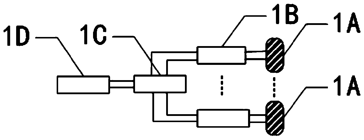
[0030] The application principle of the present invention in the radar system is as follows: figure 1 As shown, it is installed at the forefront of the phased array antenna system, and often consists of multiple 1A-spaceborne SAR dual-polarized microstrip radiating sub-array antennas to form a complete radiation surface of the phased array antenna, which is used to receive two One polarized radar reflected wave signal or two polarized microwave signals are emitted, and the two polarized radio frequency ports of the 1A-spaceborne SAR dual-polarized microstrip radiation subarray antenna are connected to a 1B-double-polarized TR component.

[0031] When the antenna system is working in the transmitting state, the 1D-receiver outputs two polarized chirp source signals, and the chirp source signals are distributed to the 1B-dual-polarized TR c...


PUM


Abstract

According to the invention, the antenna polarization requirement of a multi-information-amount satellite-borne SAR imaging system is met, reasonable unit layout combination is adopted, the problem ofmutual coupling between two polarization energies of the sub-array is isolated by using the metallized through holes, the defects of poor cross polarization and poor port isolation of a satellite-borne active phased array radiation sub-array are overcome, the space environment adaptability and reliability of the radiation sub-array are fully considered, and the aspects of material selection processing, processing selection, structural design layout and the like are fully emphasized, so that the radiation sub-array has the advantage of large-scale engineering application.

Description

technical field [0001] The invention belongs to the technical field of microwave antennas, and in particular relates to a spaceborne SAR antenna and a manufacturing method thereof. Background technique [0002] Synthetic aperture radar (SAR) detection based on spaceborne platforms has become an important means of military reconnaissance, land surveying and mapping, and earthquake relief. Compared with optical radar, SAR has the advantage of all-weather and all-weather. With the continuous development of application requirements, it becomes more urgent for SAR to have the ability to collect multi-polarization information, and the SAR antenna is a radio frequency front-end system for collecting polarization information, which plays an important role. Radiation sub-array is the basic unit of conventional SAR antenna, its performance directly determines the imaging quality of SAR system. Conventional radiation sub-arrays often adopt two forms: waveguide radiation sub-array and ...

Claims


Application Information

Patent Timeline
Patent Type & Authority Applications(China)
IPC IPC(8): H01Q1/36H01Q1/38H01Q1/50H01Q21/00
CPCH01Q1/38H01Q1/36H01Q21/00H01Q1/50
Inventor 余伟吴建军李建新沈礼
Owner CHINA ELECTRONICS TECH GRP CORP NO 14 RES INST
Why Eureka
Try Eureka