Thermally-activated delayed fluorescence emission material and application thereof
A technology of thermal activation delay and fluorescence emission, which is applied in the direction of luminescent materials, organic chemistry, chemical instruments and methods, etc., can solve the problems of poor luminescence performance of acceptor units, and achieve lower exciton density, high glass transition temperature and thermal stability performance, the effect of suppressing efficiency roll-off
- Summary
- Abstract
- Description
- Claims
- Application Information
AI Technical Summary
Problems solved by technology
Method used
Image
Examples
Embodiment (I
[0066] Implementation example (I), the synthesis of I-1 and I-2
[0067]
[0068] The chemical synthesis of intermediate M1 refers to the literature report published by the inventor (J. Mater. Chem. C., 2019, 7, 9690).
[0069] Chemical synthesis of M2:
[0070] In a three-necked flask, add 0.888 g (3 mmol) of intermediate M1, 0.682 g (3.9 mmol, 1.3 eq) of NBS, and then add 25 ml of dichloromethane and 25 ml of DMF, and react at 45 ° C after nitrogen replacement. After the reaction was monitored by TCL, dichloromethane was distilled off, methanol was added to disperse, and a solid was obtained by filtration, which was recrystallized with dichloromethane to obtain 0.9 g of pure product. M2: 1H-NMR (300MHz CDCl3): δ (ppm) 8.67-8.74 (m, 2H,), 8.10-8.17 (m, 3H), 7.72-7.76 (m, 1H), 7.61-7.67 (m, 4H) ,7.49(s,1H). M2 NMR data such as figure 1 shown.
[0071] Chemical synthesis of I-2:
[0072] In a dry three-necked flask, replace the air with nitrogen, add 0.75g of intermedi...
Embodiment (2
[0075] The synthetic scheme of implementation example (2) compound 1-20
[0076]
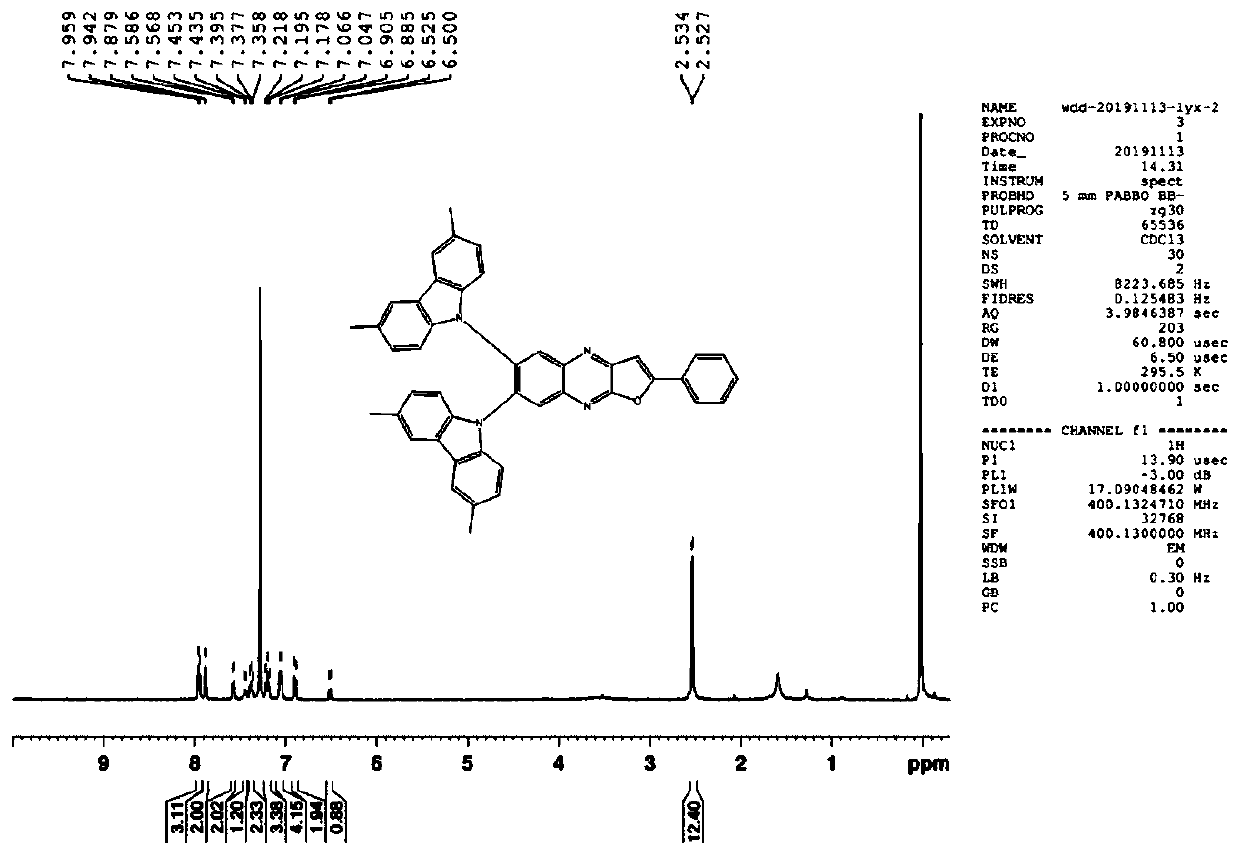
[0077] In a dry three-necked flask, add intermediate M3 (0.562g), 3,6-dimethylcarbazole (0.858g), cesium carbonate (1.63g), DMF (30ml), replace the air with nitrogen, and heat to reflux React for 14 hours. After the TCL detection reaction is completed, cool down, add 100ml of water to the reaction system, and filter to obtain a solid. The obtained solid was separated and purified by column chromatography using a mixed solvent of dichloromethane and petroleum ether as an eluent to obtain 0.3 g of I-20 product. M3 NMR data such as Figure 4 shown.
[0078] I-20: 1H-NMR (300MHz CDCl3): δ (ppm) 7.942-7.959 (m, 3H,), 7.875 (s, 2H), 7.568-7.586 (m, 2H), 7.435-7.453 (m, 1H) ,7.358-7.395(m,2H),7.178-7.218(m,3H),7.047-7.066(m,4H),6.885-6.905(m,2H),6.500-6.525(t,1H),2.527-2.534( d, 12H). The NMR data of I-20 is as follows Figure 5 shown.
Embodiment (3
[0079] Implementation example (3), the synthesis of I-33
[0080]
[0081] Synthesis of Intermediate M4
[0082] In a dry three-necked flask, replace the air with nitrogen, add 0.7g of 2,3-dichloroquinoxaline, 1.0g of 4-ethynyltriphenylamine, and 0.123g of Pd(PPh 3 ) 2 Cl 2 , 0.033g of CuI, 9mmol of triethylamine, and 10ml of acetonitrile. After nitrogen replacement, react at 60° C. for 8 hours, then add 30 ml of trifluoroacetic acid to the reaction system, and react for 4 hours. After the TCL detection reaction was completed, 100 ml of water was added to the reaction system, and the solid was obtained by filtration. The obtained solid was separated and purified by column chromatography using a mixed solvent of dichloromethane and petroleum ether as an eluent to obtain 1.0 g of M4 product.
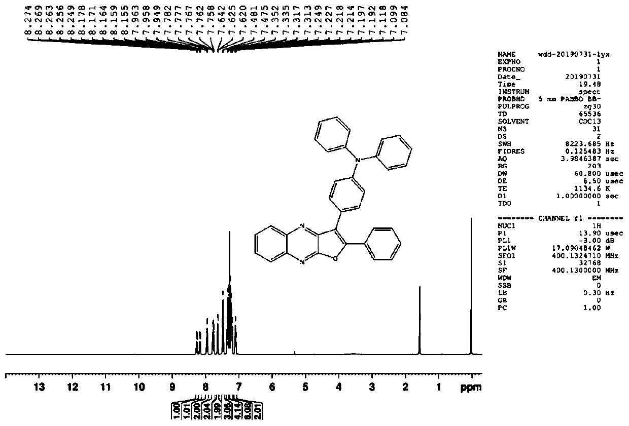
[0083] M4: 1H-NMR (300MHz CDCl3): δ (ppm) 8.188-8.208 (d, J = 8Hz, 1H,), 8.115-8.133 (d, J = 7.2Hz, 3H), 7.874-7.896 (d, J = 7.2Hz, 2H), 7.739-7.766(m, 2H), 7.348-7.386(m, 4H), 7....
PUM
 Abstract
Description
Claims
Application Information
 - R&D Engineer
- R&D Manager
- IP Professional
- Industry Leading Data Capabilities
- Powerful AI technology
- Patent DNA Extraction
Browse by: Latest US Patents, China's latest patents, Technical Efficacy Thesaurus, Application Domain, Technology Topic, Popular Technical Reports.
© 2024 PatSnap. All rights reserved.Legal|Privacy policy|Modern Slavery Act Transparency Statement|Sitemap|About US| Contact US: help@patsnap.com


