
Method for manufacturing electrode window and semiconductor device with electrode window

A manufacturing method and electrode window technology, applied in the field of semiconductors, can solve the problems of high manufacturing difficulty and high lithography precision requirements, and achieve the effect of low etching precision requirements

Active Publication Date: 2021-06-15
SUZHOU JUZHEN PHOTOELECTRIC
View PDF0 Cites 0 Cited by
  • Summary
  • Abstract
  • Description
  • Claims
  • Application Information

AI Technical Summary

Problems solved by technology

[0004] Therefore, the technical problem to be solved by the present invention is to overcome the defects in the prior art that opening electrode windows on the top of the ridge waveguide requires high photolithographic precision and high difficulty in preparation.

Method used


Image

  • Method for manufacturing electrode window and semiconductor device with electrode window
  • Method for manufacturing electrode window and semiconductor device with electrode window
  • Method for manufacturing electrode window and semiconductor device with electrode window

Examples


Embodiment 1

[0061] This embodiment provides a method for manufacturing the electrode window 7, comprising the following steps:

[0062] S1, on the first surface 1a of the semiconductor body 1, make the protruding protruding portion 2, the outer surface of the protruding portion 2 has a top region 2a opposite to the first surface 1a and a vertical wall connected to both ends of the top region 2a. Area 2b; as follows:

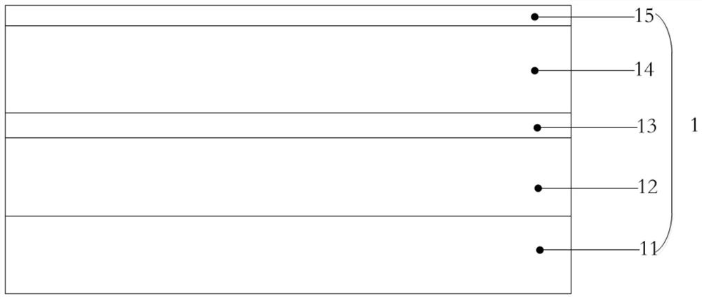
[0063] S11, such as figure 1 As shown, a semiconductor body 1 having a first surface 1a is provided, and the semiconductor body 1 is obtained by sequentially growing a first confinement layer 12, an active layer 13, a second confinement layer 14 and an electrode contact layer 15 on a substrate 11, The side surface of the electrode contacting away from the substrate 11 is the first surface 1a. The epitaxial growth method can choose vapor phase epitaxy (MOCVD), molecular beam epitaxy (MBE), low pressure chemical vapor deposition (LPCVD) and so on. Materials for forming the ...

Embodiment 2

[0080] This embodiment provides a method for manufacturing a semiconductor device with an electrode window 7, comprising the following steps:

[0081] 1. Obtain the semiconductor body 1 with the electrode window 7 opened by the manufacturing method provided in the first embodiment.

[0082] 2. If Figure 13 As shown, the metal electrode 8 is made on the side of the semiconductor body 1 where the raised portion 2 is formed. The deposition method can be electron gun vacuum evaporation, thermal evaporation, spin coating, sputtering, etc., to form a metal electrode 8 located in the electrode window 7. The first metal electrode 81, the second metal electrode 83 located on the insulating layer 3 covering the first surface 1a, and extending from the surface of the first metal electrode 81 to the outside of the vertical region 2b of the protrusion 2 to the surface of the second electrode 83 The metal connection part 82. Specifically, the metal connection portion 82 of the metal elec...


PUM


Abstract

The invention discloses a method for manufacturing an electrode window, which comprises the following steps: making an outwardly protruding protrusion on the first surface of a semiconductor body; preparing an insulating layer and planarizing in sequence on the side where the protrusion is formed on the semiconductor body layer, the insulating layer covers the outer surface of the protrusion and has a first color different from the planarization layer; the planarization layer covers the insulating layer, and the vertical area and the outer space of the first surface, and is in the area near the top of the protrusion forming a continuous plane on one side of the planarization layer; performing an etching process, the etching process includes performing an etching process on the continuous plane of the planarization layer until the insulating layer having a first color is exposed; and performing an etching process on the exposed insulating layer Etching process, a second etching process for forming an opening exposing the top region of the protrusion. The above manufacturing method can manufacture the electrode window by automatic alignment etching, which reduces the difficulty of manufacturing the electrode window, and is suitable for opening the electrode window on the ridge waveguide device with narrow line width.

Description

technical field [0001] The invention relates to the technical field of semiconductors, in particular to an electrode window and a method for manufacturing a semiconductor device with the electrode window. Background technique [0002] Semiconductor optical devices represented by semiconductor lasers, semiconductor optical amplifiers, etc., use semiconductor materials to form an active region, and the active region is stimulated to generate electromagnetic radiation to emit laser light to achieve its optical performance. Due to the advantages of low power consumption, long service life, high electro-optical conversion efficiency, and wide coverage of wavelength bands, semiconductor optical devices can be widely used in fiber optic communications, laser storage, laser display, laser marking, machining, biomedicine and Military and other fields. [0003] In the design and manufacture of semiconductor optical devices, in order to better realize the confinement of carriers and l...

Claims


Application Information

Patent Timeline
Patent Type & Authority Patents(China)
IPC IPC(8): H01S5/024H01S5/028H01S5/042H01S5/22
CPCH01S5/02461H01S5/028H01S5/0425H01S5/22
Inventor 不公告发明人
Owner SUZHOU JUZHEN PHOTOELECTRIC
Learn More