Transceiving integrated all-optical ultrasonic transducer device and preparation method thereof

An ultrasonic transducer, an integrated technology, applied in the direction of fluid using vibration, etc., can solve the problems of increasing the complexity of photoacoustic signal processing, increasing the spatial resolution of imaging, and high device packaging accuracy, so as to achieve technological feasibility, Good for acoustic wave imaging and compact package structure

Active Publication Date: 2020-05-08
HUAZHONG UNIV OF SCI & TECH
View PDF5 Cites 11 Cited by
  • Summary
  • Abstract
  • Description
  • Claims
  • Application Information

AI Technical Summary

Problems solved by technology

At the same time, relying on advanced micro-nano processing technology, it is also expected to further reduce the size of the transducer, thereby increasing the spatial resolution of imaging, and can greatly improve the low sensitivity and poor anti-interference faced by traditional ultrasonic transducers. And other issues
[0003] The current ultrasonic transducer structure based on the photoacoustic effect mainly adopts the design of the separation of acoustic emission and acoustic reception functions, such as "a scanner-free wide-field photoacoustic endoscope and imaging system" (Patent Publication No. CN108852262A) , on the one hand, this mode increases the complexity of photoacoustic signal processing in the imaging process, on the other hand, it requires higher device packaging accuracy and requires a larger package size, which is not conducive to device miniaturization

Method used


Image

  • Transceiving integrated all-optical ultrasonic transducer device and preparation method thereof
  • Transceiving integrated all-optical ultrasonic transducer device and preparation method thereof
  • Transceiving integrated all-optical ultrasonic transducer device and preparation method thereof

Examples


Embodiment 1

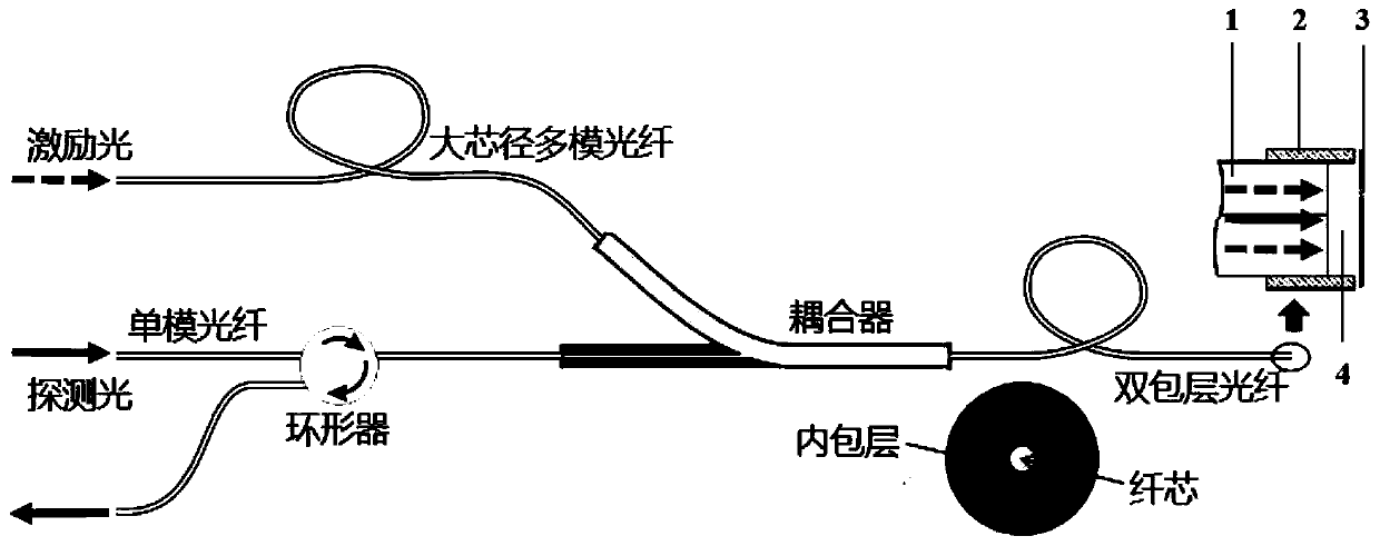
[0041] figure 1 A schematic diagram of the transceiver-integrated all-optical transducer device in Embodiment 1 is shown.

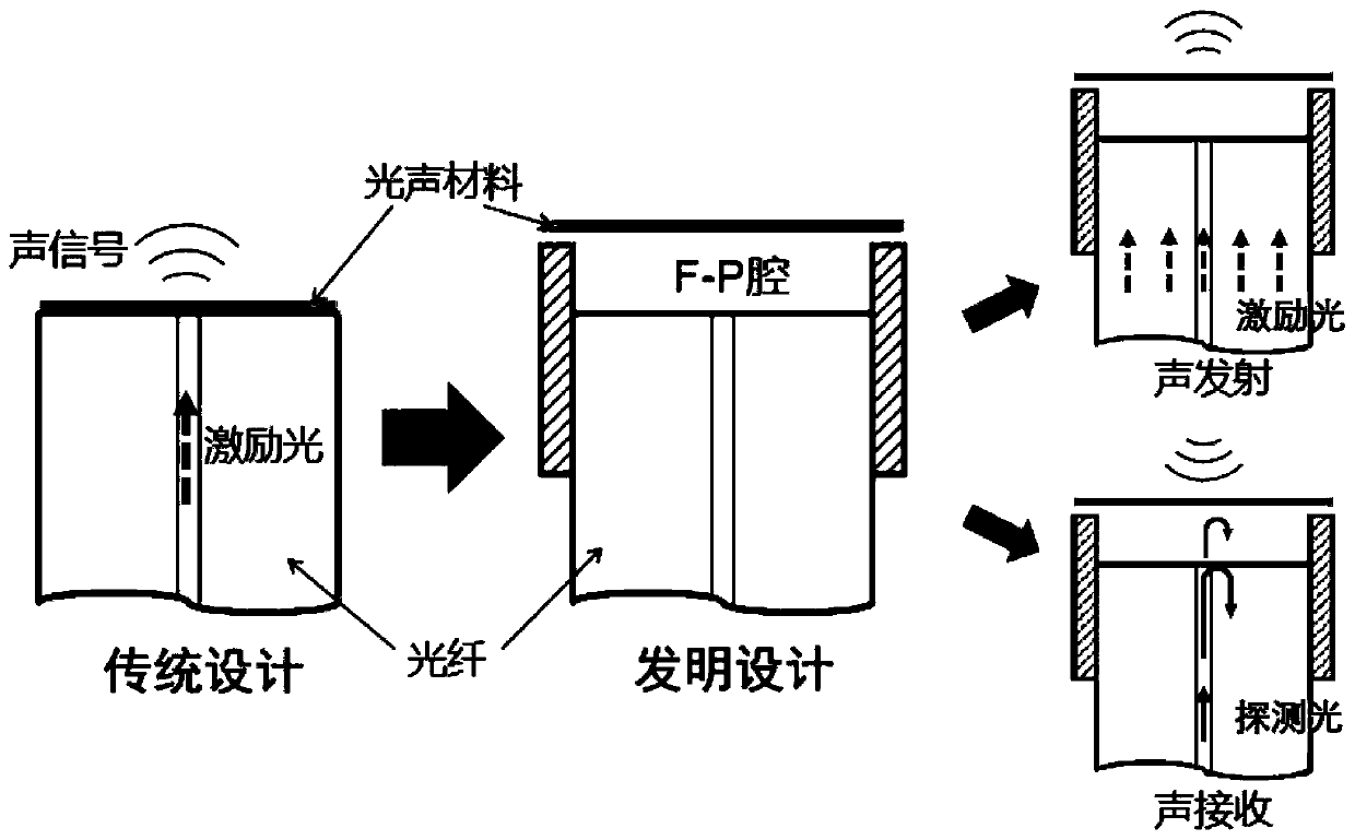
[0042] Such as figure 1 As shown, the transceiver integrated all-optical ultrasonic transducer device includes: a double-clad optical fiber 1, a structured base 2, and a suspended membrane 3; the inner wall of the structured base 2 has the same shape as the side of the cylinder, and can The outer wall of the fiber sleeve (such as ceramic sleeve or metal sleeve) that fixes the double-clad optical fiber 1 fits (the fiber sleeve is in figure 1 not shown). Wherein, the cladding of the double-clad fiber 1 is used to transmit excitation light, and the core is used to transmit probe light; the structured base 2 is used to fix the double-clad fiber and the suspension film, and is connected with The exit end faces jointly define the cavity length of the F-P cavity (the exit end face of the double-clad fiber is perpendicular to the optical axis, and the distance...

Embodiment 2

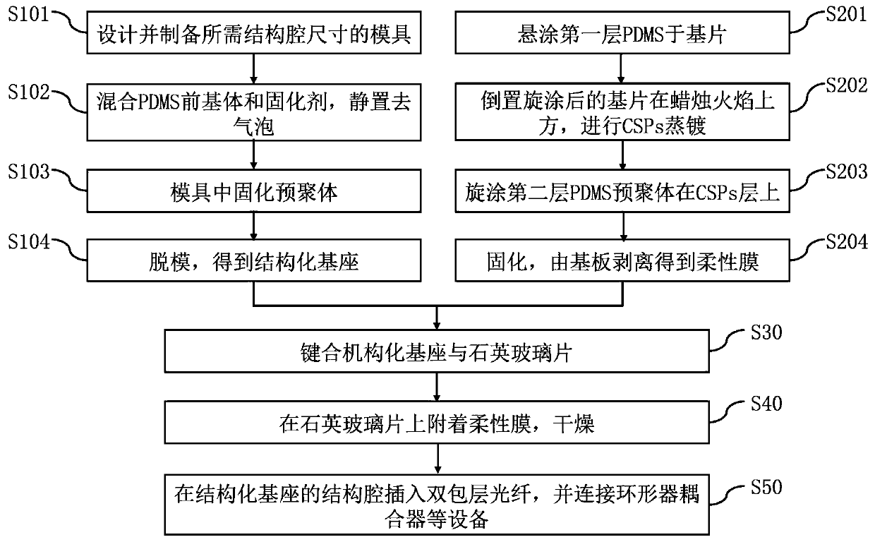
[0076] This embodiment is substantially the same as Embodiment 1, except that the sandwich structure of PDMS—candle soot carbonnanoparticles (CSPs)—PDMS does not require an additional composite glass.

[0077] At this time, steps S30 and S40 of the preparation method of Example 1 need to be adjusted as follows as a whole, and other steps S10, S201, S202, S203, and S50 remain unchanged, and step S204 does not need to be performed at the same time:

[0078] S30, bonded structured base and flexible membrane:

[0079] Specifically, the second PDMS layer of the substrate in S203 is bonded to the open cavity surface of the base to obtain a joint body 1 .

[0080] At this time, the sealing of the structural cavity is realized by an irreversible bonding process between the PDMS colloid (corresponding to the structured base 2 ) and the PDMS colloid (corresponding to the suspension film 3 ). The bonding process and precautions are the same as in Example 1.

[0081] S40, separating the...

Embodiment 3

[0083] This embodiment is substantially the same as Embodiment 2. The sandwich structure of PDMS—candle soot carbonnanoparticles (CSPs)—PDMS is directly bonded to the PDMS surface (i.e., the open cavity surface) of the structured base, except that the sandwich The outside of the type structure is additionally provided with quartz glass, which can make the device structure cavity obtain higher rigidity, so as to meet the application occasions that require other requirements for mechanical strength.

[0084] At this time, compared with Example 2, the preparation method remains unchanged in steps S10, S20, S30, and S50:

[0085] The substrate mentioned in S20 needs to be preferably a thin quartz glass sheet, such as a quartz glass layer with a thickness of 50-200um (the specific material, thickness, and characteristics can be changed according to the application scenario).

[0086] S40 does not need to be performed, and the combination 1 obtained in S30 is equivalent to the combi...


PUM


Abstract

The invention belongs to the technical field of photoacoustic detection, and discloses a transceiving integrated all-optical ultrasonic transducer device and a preparation method thereof. The device comprises a structured base (2), a suspension film (3), a double-clad fiber (1) and an F-P cavity (4), wherein the F-P cavity is constructed by the cooperation of the structured base, the suspension film and the double-clad fiber; the suspension film is a composite photoacoustic conversion film, laser beam energy of an excitation light can absorbed and the laser beam energy can be converted into ultrasonic waves which is emitted outwards, and transmission of sound waves are realized; and meanwhile, the ultrasonic echo can be received, acoustic wave return signals are sensed by deformation, thecavity length of the F-P cavity and the returned detection optical signals are influenced, and the returned detection optical signals are detected, so that receiving of sound waves can be realized. According to the invention, the structures of all components and the cooperation working mode of the components are improved, the whole process of ultrasonic transmission and reception can be completedon one suspension film by utilizing the suspension film and the F-P cavity which is further constructed, the device is more compact in structure, the photoacoustic imaging operation is simpler, and the result is more accurate.

Description

technical field [0001] The invention belongs to the technical field of photoacoustic detection, and more specifically relates to a transceiver integrated all-optical ultrasonic transducer device and a preparation method thereof. The device is a transceiver-integrated photoacoustic detector device based on the all-optical method. Background technique [0002] Ultrasonic transducers are energy conversion devices that work in the ultrasonic frequency range and can transmit ultrasonic signals and convert acoustic signals in the external sound field into other signals (such as electrical signals). Ultrasound is widely used in industry, agriculture, national defense, biomedicine, and scientific research due to its strong penetrating power, good clustering, large amount of information carrying, and easy realization of fast and accurate online non-destructive testing and non-destructive diagnosis. The new ultrasonic transducer based on the photoacoustic effect has gradually become a...

Claims


Application Information

Patent Timeline
Patent Type & Authority Applications(China)
IPC IPC(8): B06B1/00
CPCB06B1/00
Inventor 余洪斌朱昊波李琦
Owner HUAZHONG UNIV OF SCI & TECH
Why Eureka
Try Eureka