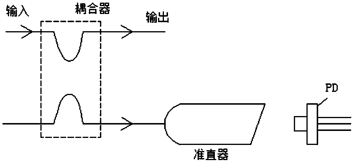
Optical fiber power monitoring structure
A technology of power monitoring and optical fiber, which is applied in the field of optical fiber power monitoring structure, can solve the problems of high assembly requirements, large additional loss, and high loss, and achieve the effects of being conducive to integrated development, simple packaging structure, and low loss
- Summary
- Abstract
- Description
- Claims
- Application Information
AI Technical Summary
Problems solved by technology
Method used
Image
Examples
Embodiment 1
[0025] Example 1, such as Figure 4 As shown, the fiber grating 2 provided on the fiber core 1 is a group, and the photosensitive receiving element 3 is a CCD detector or a PD detector. In this embodiment, the light passing direction between the fiber grating 2 and the fiber core 1 is 45°, and the light intensity of the fiber grating 2 is reflected, and part of the light intensity separated from the side of the fiber is received and combined with the photosensitive receiving element 3 to form a power monitor with a simple structure.
Embodiment 2
[0026] Example 2, on the basis of Example 1, such as Figure 5 As shown, there are more than two groups of fiber gratings 2 arranged on the core 1 and the periods of the fiber gratings 2 of different groups are different from each other. According to the different periods of different groups of fiber gratings 2, it is possible to monitor the power or energy of multiple band optical signals.
Embodiment 3
[0027] Example 3, on the basis of Example 1, such as Image 6 As shown, the fiber grating 2 is a long-period chirped grating, which can be used with a CCD or PD detector array to monitor the power or energy of a wide-band optical signal.
PUM
 Abstract
Description
Claims
Application Information
 - R&D
- Intellectual Property
- Life Sciences
- Materials
- Tech Scout
- Unparalleled Data Quality
- Higher Quality Content
- 60% Fewer Hallucinations
Browse by: Latest US Patents, China's latest patents, Technical Efficacy Thesaurus, Application Domain, Technology Topic, Popular Technical Reports.
© 2025 PatSnap. All rights reserved.Legal|Privacy policy|Modern Slavery Act Transparency Statement|Sitemap|About US| Contact US: help@patsnap.com


