Sub-aperture central liquid supply optical surface serial machining process and tool

An optical surface and processing tool technology, applied in optical surface grinders, manufacturing tools, grinding tools, etc., can solve the problems of affecting the quality of optical imaging, lack of effective control of surface damage suppression ability, energy loss, etc., to improve processing accuracy and polishing. Efficiency, reduced setup time, improved machining efficiency

Active Publication Date: 2020-04-28
TIANJIN UNIV
View PDF12 Cites 6 Cited by
  • Summary
  • Abstract
  • Description
  • Claims
  • Application Information

AI Technical Summary

Problems solved by technology

Otherwise, its high-frequency and low-frequency errors will cause imaging such as spherical aberration, aberration, and distortion to affect the optical imaging quality, and high-frequency errors will cause energy loss in the application of strong light optical components
The above-mentioned optical glass surface molding methods are mainly aimed at the optical surface surface processing technology and method, but lack the effective control of the error in the entire frequency range from low frequency to high frequency on the surface of large-aperture aspheric optical elements and the ability to suppress surface damage after processing

Method used


Image

  • Sub-aperture central liquid supply optical surface serial machining process and tool
  • Sub-aperture central liquid supply optical surface serial machining process and tool
  • Sub-aperture central liquid supply optical surface serial machining process and tool

Examples


Embodiment Construction

[0032] The present invention will be further described below with reference to the accompanying drawings and specific embodiments, but the following embodiments do not limit the present invention by any means.

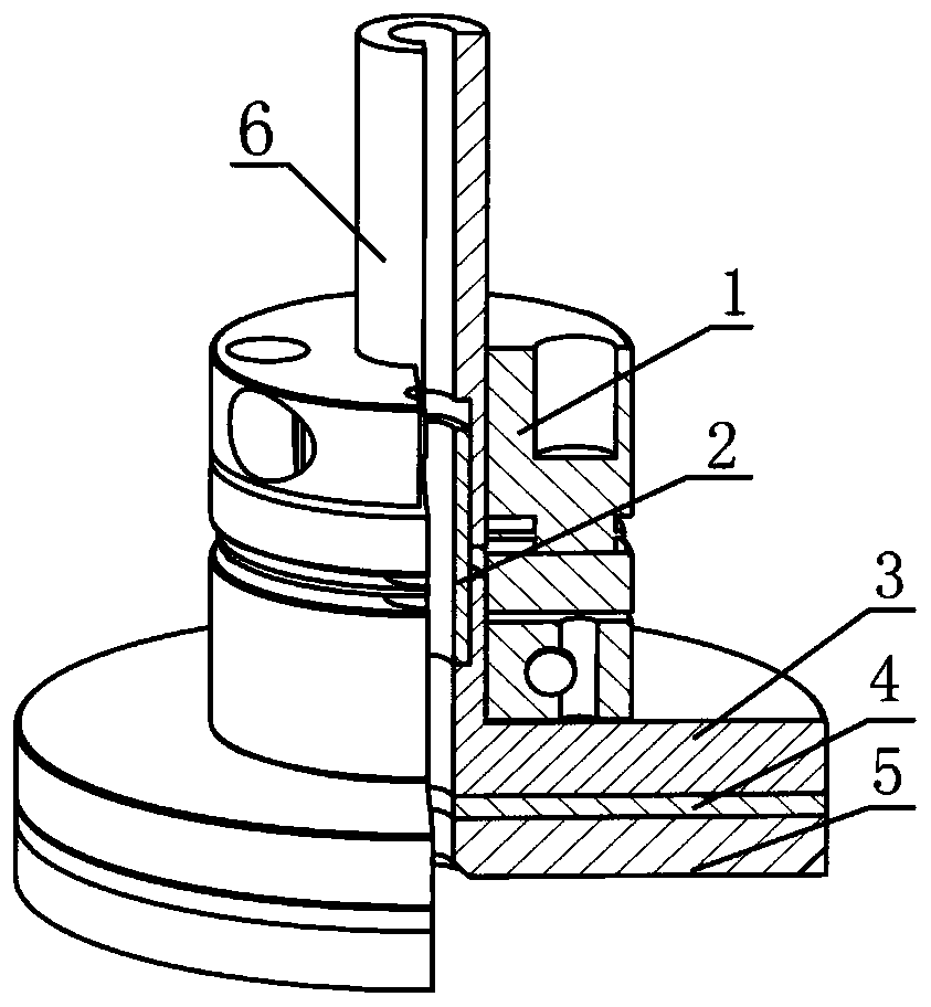
[0033] like figure 1 As shown, a sub-aperture center liquid supply optical surface processing tool proposed by the present invention includes an elastic coupling 1, a polishing disc 3 and a polishing pad 5. One end of the polishing disc 3 is a connecting shaft segment, and the polishing disc 3 The other end of the polishing disk 3 is the disk surface, the size of the polishing disk 3 is between 1 / 5 and 1 / 10 of the size of the optical element to be processed, and the diameter of the polishing disk 3 can range from 10 to 100 mm; one end of the flexible coupling 1 A rotating shaft 6 is connected, the other end of the flexible coupling 1 is connected to the polishing disc 3, and the disc surface of the polishing disc 3 is bonded to the polishing pad 5 through the elastic b...


PUM

PropertyMeasurementUnit
particle diameteraaaaaaaaaa
depthaaaaaaaaaa

Abstract

The invention discloses a sub-aperture central liquid supply optical surface serial machining process. The serial machining process is a systematic machining method from a blank surface to an ultra-smooth surface based on a hydrodynamic pressure principle and mainly comprises a hydrodynamic pressure consolidation abrasive grinding and polishing process, a central liquid supply small grinding headpolishing process and a disc-type hydrodynamic pressure polishing process. A sub-aperture central liquid supply optical surface machining tool comprises an elastic coupler, a polishing disc and a polishing pad, wherein the two ends of the flexible coupler are respectively connected with the polishing disc and a rotating shaft; and successive recursion inhibition processes of low-frequency, medium-frequency and high-frequency errors of the optical surface are achieved by replacing different grinding pads and polishing pads on the same machining tool. Meanwhile, in order to obtain a high-qualityand low-damage ultra-precision smooth surface, different grinding pads and polishing pads are combined to use, the residual sub-surface damage layer on the surface after being polished in premier polishing process is removed, no new sub-surface damage is generated any more, and the sub-surface damage is reduced to the minimum through multiple machining processes.

Description

technical field [0001] The invention belongs to the field of optical processing, and relates to a series of processing techniques for ultra-smooth optical surfaces based on the principle of fluid dynamic pressure, in particular to a systematic technique for processing optical surfaces from grinding surfaces to ultra-smooth surfaces. Background technique [0002] Optical glass is widely used in aerospace, information, energy, chemical, microelectronics and other fields due to its high transparency, optical uniformity, and stable chemical properties. With the vigorous development of optical technology and the increasingly wide application of optical materials, higher requirements are placed on the surface quality of optical components. Especially for high-power laser device systems, micro-electromechanical systems and other large-scale optical systems, the surface quality and processing efficiency of components are extremely demanding. Micron-level processing accuracy and nano...

Claims


Application Information

Patent Timeline
Patent Type & Authority Applications(China)
IPC IPC(8): B24B37/11B24B37/34B24B13/01B24B57/02B24B1/00
CPCB24B37/11B24B37/34B24B13/01B24B57/02B24B1/00
Inventor 林彬姜向敏曹中臣黄田李世鹏
Owner TIANJIN UNIV
Why Eureka
Try Eureka