Multistage built-in heat source and multistage waste heat recycling type cereal drying tower

A technology of waste heat recovery and drying tower, which is applied in drying, drying machines, grain drying, etc., to achieve the effects of reducing treatment costs, reducing exhaust gas emissions, and simple structure

Pending Publication Date: 2020-04-17
ZHENGZHOU WANGU MACHINERY
View PDF0 Cites 2 Cited by
  • Summary
  • Abstract
  • Description
  • Claims
  • Application Information

AI Technical Summary

Problems solved by technology

[0011] Aiming at the defects in the prior art, the present invention provides a multi-stage built-in heat source and multi-stage...

Method used


Image

  • Multistage built-in heat source and multistage waste heat recycling type cereal drying tower
  • Multistage built-in heat source and multistage waste heat recycling type cereal drying tower
  • Multistage built-in heat source and multistage waste heat recycling type cereal drying tower

Examples


Embodiment 1

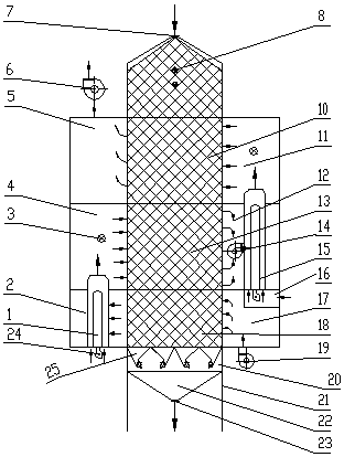
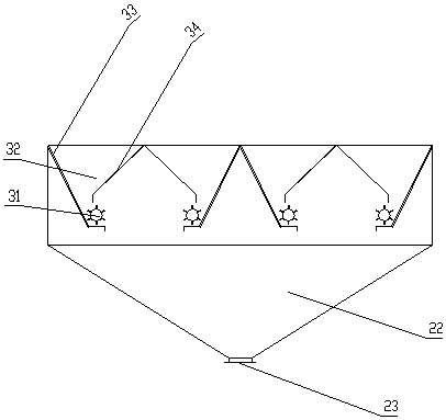
[0036] see figure 1 , image 3 and Figure 4The second-level built-in heat source and second-level waste heat recovery type grain drying tower provided by Embodiment 1 of the present invention includes a tower body with a rectangular cross-section installed vertically on the base 21, and a feed inlet 7 is arranged on the top of the tower body. The bottom of the tower body is provided with a discharge port 23, and the inside of the tower body is sequentially provided with a grain storage section 9, a drying section 10, a drying section 2 13, a cooling section 18, a grain discharge section 20 and a grain discharge hopper 22. The feed port 7 is connected to the grain storage section 9, the discharge port 23 is connected to the grain discharge hopper 22, the grain discharge section 20 is equipped with a six-impeller type grain discharge mechanism 25, and the left side of the tower corresponding to the drying section 10 is provided with an exhaust gas chamber 3. The hot air chamb...

Embodiment 2

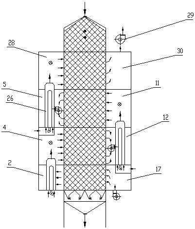
[0049] see figure 2 , the schematic diagram of the structure of the three-stage built-in heat source and three-stage waste heat recovery and utilization type grain drying tower provided in this embodiment, its structure is basically the same as that of Embodiment 1, the difference is that Embodiment 1 is a two-stage built-in heat source and two-stage waste heat utilization type grain drying tower. The drying tower, the second embodiment is a three-stage built-in heat source and three-stage waste heat utilization type grain drying tower, and the second embodiment has one more drying section than the first embodiment. Such as figure 2 As shown, the left side of the tower body corresponding to the drying section and the cooling section is provided with hot air chamber four 28, waste gas chamber three 5, hot air chamber one 4 and waste gas chamber one 2 from top to bottom, and the towers corresponding to the drying section and cooling section On the right side of the body, exha...


PUM


Abstract

A multistage built-in heat source and multistage waste heat recycling type cereal drying tower comprises a tower body and a plurality of air chambers. A cereal storage section, a multistage drying section, a cooling section, a cereal discharging section and a cereal discharging hopper are sequentially arranged in the tower body from top to bottom. The air chambers matched with the multistage drying section and the cooling section are arranged at the positions, on the tower body, of the left side and the right side of the multistage drying section and the cooling section from top to bottom. Theair chambers are divided into waste gas chambers, hot air chambers and cold air chambers according to functions, and the air chambers located on the left side are alternately and sequentially arranged from the waste gas chamber and the hot air chamber. The cold air chamber is arranged on the lowermost layer of the air chambers located on the right side, and the waste gas chamber and the hot air chamber are alternately and sequentially arranged above the cold air chamber. A hot blast heater is arranged in the vertically adjacent waste gas chamber and hot air chamber of the cereal discharging section, the hot blast heater is one or more of upright direct-fired hot blast heaters, an air outlet of the hot blast heater is formed in the hot air chambers, and an air inlet of the hot blast heateris formed in the waste gas chambers. The multistage built-in heat source and multistage waste heat recycling type cereal drying tower can achieve the aims of reducing energy consumption and reducingemission pollution.

Description

technical field [0001] The invention relates to drying equipment in the field of grain drying, in particular to a multi-stage built-in heat source and multi-stage waste heat recovery type grain drying tower. Background technique [0002] Grain drying tower is a kind of mechanized grain drying equipment, which is used for drying operation of freshly harvested wet grain. [0003] At present, the types of grain drying towers widely used in my country are mainly continuous tower drying towers, all of which adopt convective thermal drying. The temperature of the grain rises, the internal water vaporizes and evaporates, and the exhaust gas after heat release takes the water vapor out of the drying tower to achieve the purpose of grain drying. Therefore, during the grain drying process, the hot air is not only the carrier of heat transfer, but also the carrier of water, and it is discharged out of the drying tower after the drying process is completed. At the same time, the dried ...

Claims


Application Information

Patent Timeline
IPC IPC(8): F26B9/06F26B21/00F26B21/04F26B25/00A23B9/08
CPCA23B9/08F26B9/063F26B21/001F26B21/004F26B21/04F26B25/00F26B2200/06Y02A40/90Y02P60/85Y02P70/10
Inventor 郭桂霞陆学中张德榜
Owner ZHENGZHOU WANGU MACHINERY
Why Eureka
Try Eureka