
Punching process of sheet metal part

A technology of sheet metal parts and punching, which is applied in the field of mold manufacturing, can solve the problems of life-threatening threats to staff, reduce stamping work efficiency, etc., and achieve the effect of improving safety and processing quality of parts, improving work efficiency, and ensuring strength requirements

Active Publication Date: 2020-04-17
TONGLING ZHAOLIN IND & TRADE CO LTD
View PDF9 Cites 0 Cited by
  • Summary
  • Abstract
  • Description
  • Claims
  • Application Information

AI Technical Summary

Problems solved by technology

[0003] However, during the use of the stamping dies currently on the market, the scraps or blanks that are punched out need to be picked up manually, which not only poses a threat to the life of the staff, but also reduces the working efficiency of stamping.

Method used


Image

  • Punching process of sheet metal part
  • Punching process of sheet metal part
  • Punching process of sheet metal part

Examples


Embodiment approach

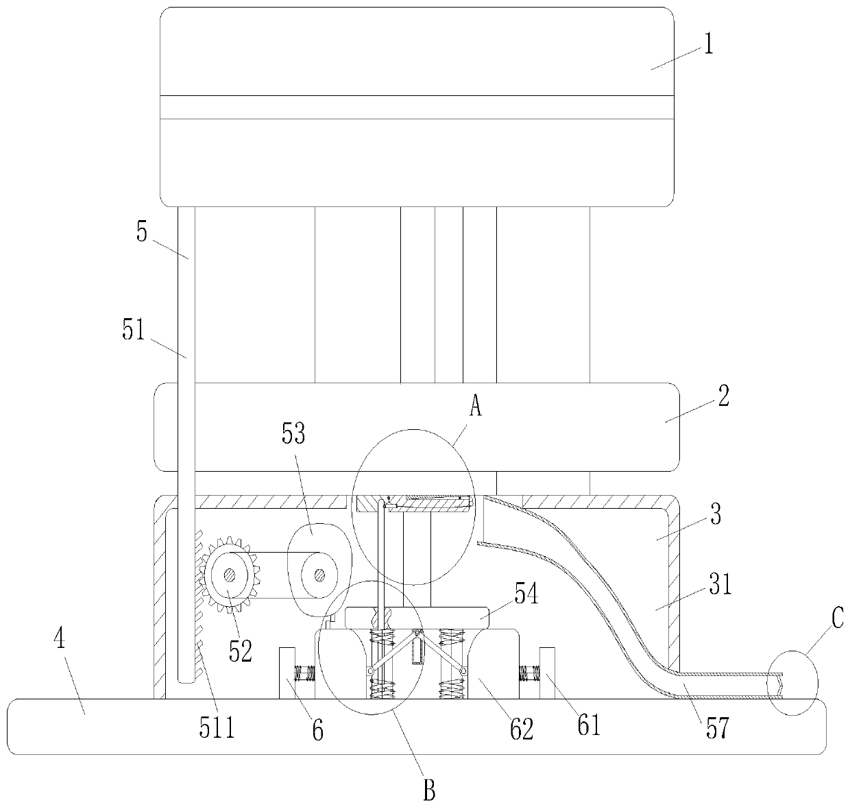
[0032] As an embodiment of the present invention, the side wall of the cam 53 close to the bottom side of the cavity 31 is provided with a No. 1 push block 531; the cavity 31 is provided with a reinforcement unit 6; the reinforcement unit 6 includes a baffle plate 61 and a spacer 62; the baffle 61 is symmetrically fixed on the bottom side of the cavity 31 near the first plate 54, and the baffle 61 is provided with a second push block 611 near the first push block 531; the spacer 62 It is connected with the side wall of the block by a spring; the bottom end of the first plate 54 is provided with a chute plate 541; the chute plate 541 is slidably connected with a hinge rod 542; the two ends of the hinge rod 542 are hinged on the pad On the side wall of block 62; through the cooperation of No. 1 push block 531, No. 2 push block 611, baffle 61 and spacer 62, the strength of the No. 1 plate 54 and No. 2 plate 55 in the stamping process is strengthened; when working, when the mold A...


PUM


Abstract

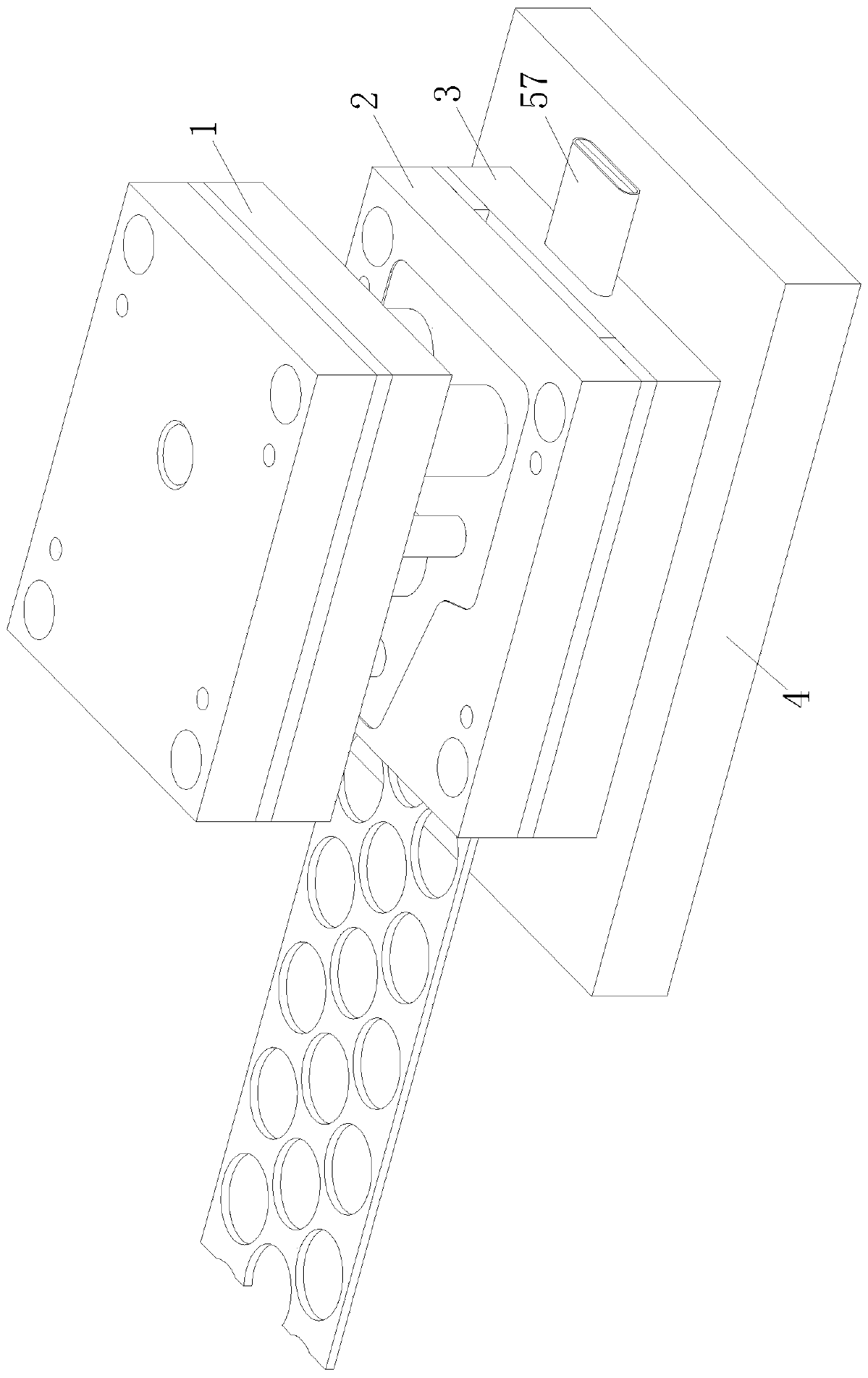
The invention belongs to the technical field of die manufacturing, and particularly relates to a punching process of a sheet metal part. A die adopted by the punching process comprises an upper die plate, a stamping plate, a bottom plate and a base, a cavity is formed in the bottom plate, and a conveying unit is arranged in the cavity. The conveying unit comprises a push rod, a gear, a cam, a first plate, a second plate, an ejector rod and a discharging pipe; one end of the ejector rod is fixed to the bottom side of the cavity, and the other end of the ejector rod penetrates through the firstplate to make contact with the bottom end of an auxiliary plate; and the discharging pipe is installed in the cavity, one end of the discharging pipe is close to the side wall, opposite to the auxiliary plate, of a main plate, and the other end of the discharging pipe extends out of the bottom plate. Through cooperation of the push rod, the gear, the cam, the first plate, the second plate, the ejector rod and the discharging pipe, after the part is stamped, discharged materials can slide out along the discharging pipe, automatic taking of the discharged materials is completed, manual taking isavoided, the labor cost in the stamping process is saved, the working efficiency is improved, and great convenience is brought to workers.

Description

technical field [0001] The invention belongs to the technical field of mold manufacturing, in particular to a punching process for sheet metal parts. Background technique [0002] Stamping die is a special process equipment that processes materials (metal or non-metal) into parts (or semi-finished products) in cold stamping, called cold stamping die (commonly known as cold stamping die). Stamping is a pressure processing method that uses a die installed on a press to apply pressure to a material at room temperature to separate or plastically deform it to obtain the desired parts. The modernization of mold manufacturing technology is the basis for the development of mold industry. With the development of science and technology, advanced technologies such as computer technology, information technology, and automation technology are continuously infiltrating, intersecting, and integrating into traditional manufacturing technologies, and transforming them to form advanced manuf...

Claims


Application Information

Patent Timeline
IPC IPC(8): B21D28/26B21D28/34B21D43/02
CPCB21D28/26B21D28/34B21D43/027
Inventor 卢兆林卢小升卢云霞
Owner TONGLING ZHAOLIN IND & TRADE CO LTD
Learn More