Luneberg lens, low-profile array antenna based on Luneberg lens array and satellite antenna

A technology of Lumberg lens and array antenna, which is applied in the field of antennas to achieve the effects of easy cost control, strong market adaptability, and simplified feeding network

Inactive Publication Date: 2020-04-14
HEFEI RHOSOON INTELLIGENT TECH CO LTD
View PDF5 Cites 10 Cited by
  • Summary
  • Abstract
  • Description
  • Claims
  • Application Information

AI Technical Summary

Problems solved by technology

[0006] At present, there is no report on an array antenna with large-angle scanning and communication functions based on Lunberg lens array

Method used


Image

  • Luneberg lens, low-profile array antenna based on Luneberg lens array and satellite antenna
  • Luneberg lens, low-profile array antenna based on Luneberg lens array and satellite antenna
  • Luneberg lens, low-profile array antenna based on Luneberg lens array and satellite antenna

Examples


Embodiment 1

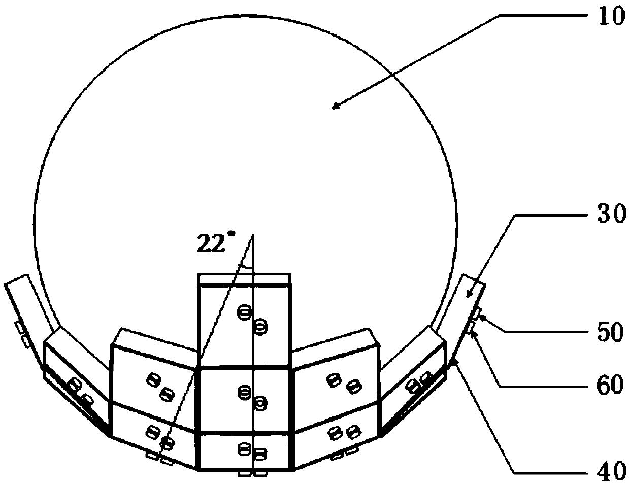
[0047] Lunberg lens unit 10, such as figure 1 , figure 2 , image 3As shown, it is a sphere with a diameter of 140 mm, which is composed of upper and lower symmetrical upper and lower hemispheres. Each hemisphere is divided into multiple layers. The more layers, the better the performance. However, considering the difficulty of processing, this example gives 12 layers. Each layer is composed of three-dimensional cross unit structure. The center of each cross unit is a cube, and from the outer edge of the sphere to the center, the volume of the cube becomes larger and larger, so that the Lunberg lens unit 10 is a dielectric sphere antenna with a gradient permittivity structure, which can transmit light from all directions. The microwave signal converges to a point on the surface of the lens, which can realize the convergence and directional emission of electromagnetic waves. Its dielectric constant distribution satisfies the dielectric constant distribution of a spherical L...

Embodiment 2

[0072] Compared with Embodiment 1, this embodiment has the following differences:

[0073]For the antenna unit, the upper surface metal layer 20 and the lower surface metal layer 40 are metal conductor copper with a thickness of 0.018 mm. The metal layer on the lower surface constitutes the ground of the antenna, and the size is 28mm×28mm. The dielectric substrate 30 is a rectangular RogersRT / duroid 6010 dielectric board with a dielectric constant of 10.2, a thickness of 8 mm, and a size of 28 mm×28 mm.

[0074] Curved antenna arrays, such as Figure 11 As shown, the microstrip antenna array placed on the surface of each Lunberg lens unit 10 is formed by 25 microstrip antenna units arranged along the arc surface, specifically: 7 of the 25 antenna units are arranged side by side in an arc , 5 antenna units, 3 antenna units, and 1 antenna unit are sequentially arranged outward on both sides thereof, finally forming an arc-shaped (bowl-shaped) structure.

[0075] Lumberg lense...


PUM


Abstract

The invention provides a luneberg lens. The luneberg lens comprises a luneberg lens unit and an antenna array fixed on the surface of the luneberg lens unit, and the antenna array is arranged on the circumferences of a plurality of concentric circles in a one-dimensional arc line or two-dimensional arc surface along the surface of the luneberg lens unit through a plurality of antenna units. Compared with the prior art, the antenna array is arranged on the surface of the single luneberg lens unit, large-angle beam scanning can be achieved by sequentially feeding the antenna units at the same positions in the antenna array on the surface of each luneberg lens unit, and the complexity and design difficulty of an antenna feed network are reduced. If only a certain angle or a certain directionneeds to be covered, the antenna units in other directions can be cut, so that the antenna array is simplified, the feed network is simplified, and the cost is easy to control.

Description

technical field [0001] The invention relates to the technical field of antennas, in particular to a Lunberg lens, a low-profile array antenna and a satellite antenna based on a Lunberg lens array. Background technique [0002] The beam scanning range of an array antenna is an important performance index. In 2005, "Antenna Theory: Analysis and Design" (Constantine A. Balanis, Antenna Theory: Analysis and Design, edited by Constantine A. Balanis and published by John Wiley & Sons, Inc., Hoboken, New Jersey, USA, John Wiley&Sons, Inc., Hoboken, New Jersey: 2005, Page(s): 283-384) introduced the characteristics and design methods of traditional planar phased arrays. When the traditional planar phased array antenna scans to a large angle, the gain of the array radiation pattern will decrease and the sidelobe will increase due to the reduction of the equivalent aperture of the antenna array. The scanning angle usually does not exceed ±40°, which is limited. The scanning angle li...

Claims


Application Information

Patent Timeline
Patent Type & Authority Applications(China)
IPC IPC(8): H01Q1/50H01Q3/24H01Q15/02H01Q21/00H01Q21/06H01Q21/20H01Q21/29
CPCH01Q1/50H01Q3/24H01Q15/02H01Q21/0006H01Q21/065H01Q21/20H01Q21/293
Inventor 桂万如邓庆勇朱旗夏雨龙王存季文涛
Owner HEFEI RHOSOON INTELLIGENT TECH CO LTD
Why Eureka
Try Eureka