
A double-sided preparation method of a drift detector and a drift detector

A detector, double-sided technology, applied in the field of semiconductor detectors, can solve the problems of difficult manufacturing, complex manufacturing process and process, damage to anode region and drift ring region, etc., to improve performance, reduce damage, and simplify processing equipment the effect of dependence

Active Publication Date: 2021-04-06
INST OF MICROELECTRONICS CHINESE ACAD OF SCI
View PDF9 Cites 0 Cited by
  • Summary
  • Abstract
  • Description
  • Claims
  • Application Information

AI Technical Summary

Problems solved by technology

[0003] The existing silicon drift detector adopts a double-sided process, and its manufacturing process and process are much more complicated than ordinary semiconductor devices, especially for conventional semiconductor factories that only have a single-sided photolithography process.
When the first isolation layer on the surface of the semiconductor substrate is etched by a dry etching process, it is easy to cause certain damage to the anode region and the drift ring region to be formed, thereby affecting the operating voltage, dark current and reliability of the drift detector.

Method used


Image

  • A double-sided preparation method of a drift detector and a drift detector
  • A double-sided preparation method of a drift detector and a drift detector
  • A double-sided preparation method of a drift detector and a drift detector

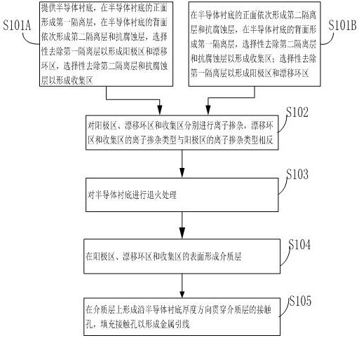
Examples


Embodiment Construction

[0022] The specific implementation manners according to the present invention will be described below in conjunction with the accompanying drawings.

[0023] In the following description, many specific details are set forth in order to fully understand the present invention, but the present invention can also be implemented in other ways different from those described here, therefore, the present invention is not limited to the specific embodiments disclosed below limit.

[0024] When the first isolation layer on the surface of the semiconductor substrate is etched by a dry etching process, it is easy to cause certain damage to the anode region and the drift ring region to be formed, thereby affecting the operating voltage, dark current and reliability of the drift detector. .

[0025] Based on this, the present invention proposes a double-sided preparation method for drift detectors. The double-sided preparation method can realize the removal of the semiconductor substrate b...


PUM

PropertyMeasurementUnit
thicknessaaaaaaaaaa
thicknessaaaaaaaaaa
thicknessaaaaaaaaaa

Abstract

The invention provides a double-sided preparation method of a drift detector, which comprises forming a first isolation layer on one side of a semiconductor substrate, sequentially forming a second isolation layer and an anti-corrosion layer on the other side of the semiconductor substrate, and selectively removing the first isolation layer. One isolating layer to form the anode region and the drift ring region, and the second isolating layer and the anti-corrosion layer are selectively removed to form the collection region; the anode region, the drift ring region and the collection region are respectively ion-doped and the semiconductor substrate is annealed ; forming a dielectric layer on the surfaces of the anode region, the drift ring region and the collection region; forming a contact hole through the dielectric layer on the dielectric layer, and filling the contact hole to form a metal lead. In the present invention, by depositing an anti-corrosion layer on the second isolation layer, the damage to the second isolation layer, the anode area and the drift ring area is reduced when the first isolation layer is removed by a wet etching process, which is beneficial to the use of single-sided light Engraving technology realizes double-sided process. The present invention also provides a drift detector obtained by applying the above double-sided preparation method.

Description

technical field [0001] The invention belongs to the field of semiconductor detectors, in particular to a double-sided preparation method of a drift detector and the drift detector. Background technique [0002] The silicon drift detector is to prepare a large-area uniform PN abrupt junction on the ray incident surface of the high-purity N-type silicon wafer, and prepare a dot-shaped N-type anode in the center of the opposite side of the ray incident surface. Surrounding it are many concentric P-type drift electrodes. When working, a reverse voltage is applied to the PN junctions on both sides of the silicon drift detector, thereby generating a potential well in the silicon drift detector body. After a potential difference is added to the P-type drift electrode, a transverse electric field will be generated in the silicon drift detector, and the transverse electric field will bend the potential well to force the electrons generated by the incident surface radiation to drift ...

Claims


Application Information

Patent Timeline
Patent Type & Authority Patents(China)
IPC IPC(8): H01L31/0352H01L31/115H01L31/18
CPCH01L31/035272H01L31/115H01L31/1804Y02P70/50
Inventor 许高博殷华湘翟琼华
Owner INST OF MICROELECTRONICS CHINESE ACAD OF SCI
Learn More