
Organic electroluminescent device

An electroluminescent element and luminescent technology, which is applied in the direction of electrical components, electric solid-state devices, circuits, etc., can solve the problems of difficult to achieve dark blue, short life, optical loss, etc.

Active Publication Date: 2020-02-21
MATERIAL SCIENCES CORPORATION
View PDF7 Cites 0 Cited by
  • Summary
  • Abstract
  • Description
  • Claims
  • Application Information

AI Technical Summary

Problems solved by technology

[0004] Among the substances used as blue dopants in the past, the use of fluorescent molecules such as perylene, coumarine, anthracene, and pyrene occupies a dominant position, but due to the luminescence of dopants The half-value width (Full width half the maximum) of the spectrum is as wide as ~40nm, so it is difficult to achieve deep blue (Deep Blue), and optical loss also occurs when the specific wavelength range is expanded by optical resonance in the top emission light-emitting element
[0005] Faced with this problem, boron-based dopants with a narrow emission spectrum and high device efficiency have been emerging in recent years, but the reality is that despite their high efficiency and excellent color reproduction, they are difficult to commercialize due to their short lifetime.

Method used


Image

  • Organic electroluminescent device
  • Organic electroluminescent device
  • Organic electroluminescent device

Examples


Synthetic example 1-1

[0143]

[0144] 8.9g (20mmol) of the starting material 1 was dissolved in butylbenzene (250ml) and then cooled to 0°C. Under a nitrogen atmosphere, 24.7 ml (42 mmol) of a 1.7 M butyllithium solution (in Pentane) was added, and the mixture was stirred at 60°C for 2 hours.

[0145] After that, the reactant was cooled to 0°C again, 4.0 ml (42 mmol) of BBr3 was added, and the mixture was stirred at room temperature for 0.5 hours. The reactant was cooled to 0°C again, and 7.3 ml (42 mmol) of N,N-diisopropylethylamine was added, followed by stirring at 60°C for 2 hours.

[0146] The reaction liquid was cooled to room temperature, and the organic layer was extracted with ethyl acetate (Ethyl acetate) and water (Water). After removing the solvent of the extracted organic layer, it was purified by silica gel column chromatography (DCM / Hexane). Then, it was recrystallized and refined using a DCM / acetone (Acetone) mixed solvent to obtain 1.7 g of the above-mentioned compound 1-1 with a yiel...

Synthetic example 1-2

[0149]

[0150] Except that 9.9 g (20 mmol) of the starting material 1-3 was used instead of the starting material 1-1, the experiment was performed in the same manner as in Synthesis Example 1-1 to obtain 2.16 g of the above compound 1- with a yield of 23.0% 3.

[0151] MS(MALDI-TOF)m / z: 470[M]+

Synthetic example 1-3

[0153]

[0154] Except that 10.6 g (20 mmol) of the starting material 1-5 was used instead of the starting material 1-1, the experiment was performed in the same manner as in Synthesis Example 1-1 to obtain 2.3 g of the above compound 1- with a yield of 23.2% 5.

[0155] MS(MALDI-TOF)m / z: 502[M]+


PUM


Abstract

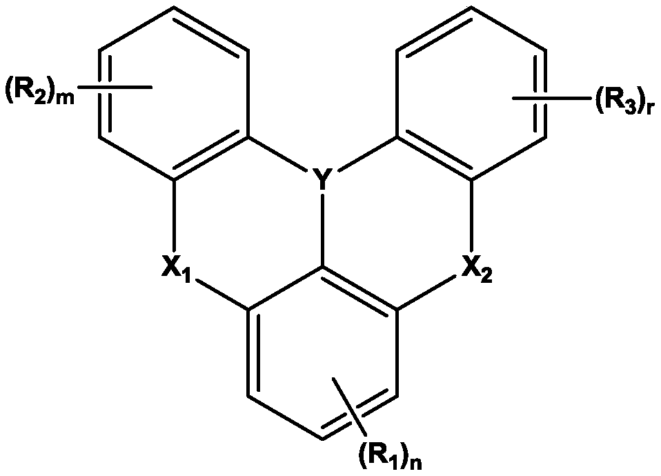
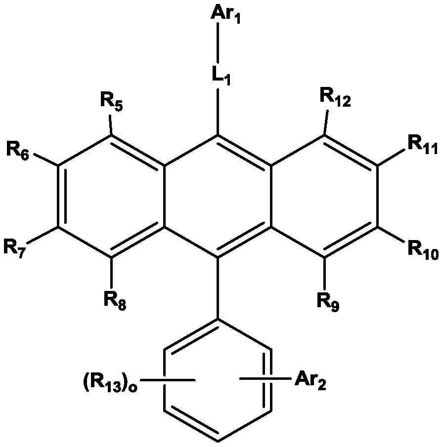
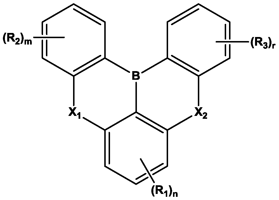
The invention relates to an organic electroluminescent element, which includes a first electrode, a second electrode, and at least one organic film between the first electrode and the second electrode. The organic film includes a light-emitting layer. The light-emitting layer includes a compound represented by chemical formulas 1 and 2, wherein n is an integer of 0 to 3; m, r, and o are the same or different from each other; 0 to 4 are integers; Y is B, N or the like; X1 and X2 are the same or different from each other and are selected from O, S and the like; R1 to R4 are the same or differentfrom each other and are selected from hydrogen, deuterium and the like; L1 is selected from a single bond, an arylene group having 5 to 30 carbon atoms and the like; Ar1 to Ar2 are the same or different from each other and are selected from a cycloalkyl having a carbon number 3 to 30 and the like; R5 to R13 are the same or different from each other and are selected from hydrogen, deuterium and the like; R1 to R13, the substituents of L1, Ar1, and Ar2 are substituted by substituents selected from hydrogen, deuterium and the like, when a plurality of substituents exist, they are the same or different from each other. The organic electroluminescent element of the present invention is excellent in efficiency, color characteristics, and lifetime.

Description

Technical field [0001] The present invention relates to an organic electroluminescence element, and more specifically, an organic electroluminescence element containing a novel boron-based organic compound and an anthracene-based organic compound in one or more organic layers included in the organic electroluminescence element. Background technique [0002] The organic electroluminescence element has a cathode (electron injection electrode) and an anode (hole injection electrode), and a structure including one or more organic layers between the two electrodes. At this time, in the organic electroluminescent element, starting from the anode, a hole injection layer (HIL), a hole transport layer (HTL), a light emitting layer (EML), Electron transport layer (ETL, electron transport layer) or electron injection layer (EIL, electron injection layer), in order to improve the efficiency of the light-emitting layer, you can add an electron blocking layer (EBL, electron blocking layer) or ...

Claims


Application Information

Patent Timeline
IPC IPC(8): H01L51/54
CPCH10K85/623H10K85/649H10K85/615H10K85/657H10K85/322H10K85/6576H10K85/6574H10K85/6572H10K50/11
Inventor 李舜昌郑在皓姜炫彬都光石金辰成郭兑虎
Owner MATERIAL SCIENCES CORPORATION
Learn More