Liquid fuel catalytic reforming device

A technology for catalytic reforming and liquid fuel, applied in inorganic chemistry, chemical instruments and methods, non-metallic elements, etc., can solve problems such as large temperature gradient, carrier cracking, limiting the overall performance of liquid fuel reforming device, etc., to improve efficiency , the effect of shortening the time

Pending Publication Date: 2020-02-14
TSINGHUA UNIV
View PDF0 Cites 2 Cited by
  • Summary
  • Abstract
  • Description
  • Claims
  • Application Information

AI Technical Summary

Problems solved by technology

Steam reforming uses water vapor as the oxidant, which has the advantages of inhibiting carbon deposition and high hydrogen content, but the entire reaction process needs to absorb a lot of heat and requires additional heating devices, often with complex systems and large volumes; partial oxidation reforming uses insufficient chemical The equivalent ratio of oxygen or air is used as the oxidant, and the conversion process releases heat, which can achieve self-sustainment under high temperature conditions, but the risk of carbon deposition in the process is high and the hydrogen content is low; autothermal reforming uses part of water vapor and air as the oxidant, which has both The above two reforming methods have advantages in system efficiency, carbon deposition, reaction temperature, etc., but the control of operating parameters is relatively complicated, and there is also a certain risk of carbon deposition
[0004] Among the three liquid fuel reforming methods, there is generally "overheating" inside the catalyst bed, that is, the temperature in the area is too high, or "undercooling", that is, the temperature in the area is too low, and the temperature gradient inside the catalyst bed is large, up to 200 The problem of ℃ / cm, which often leads to problems such as catalyst sintering, surface carbon, and support cracking, affects the catalytic performance and long-term service life of the catalyst, and severely limits the overall performance of the liquid fuel reformer

Method used


Image

  • Liquid fuel catalytic reforming device
  • Liquid fuel catalytic reforming device
  • Liquid fuel catalytic reforming device

Examples


Embodiment 1

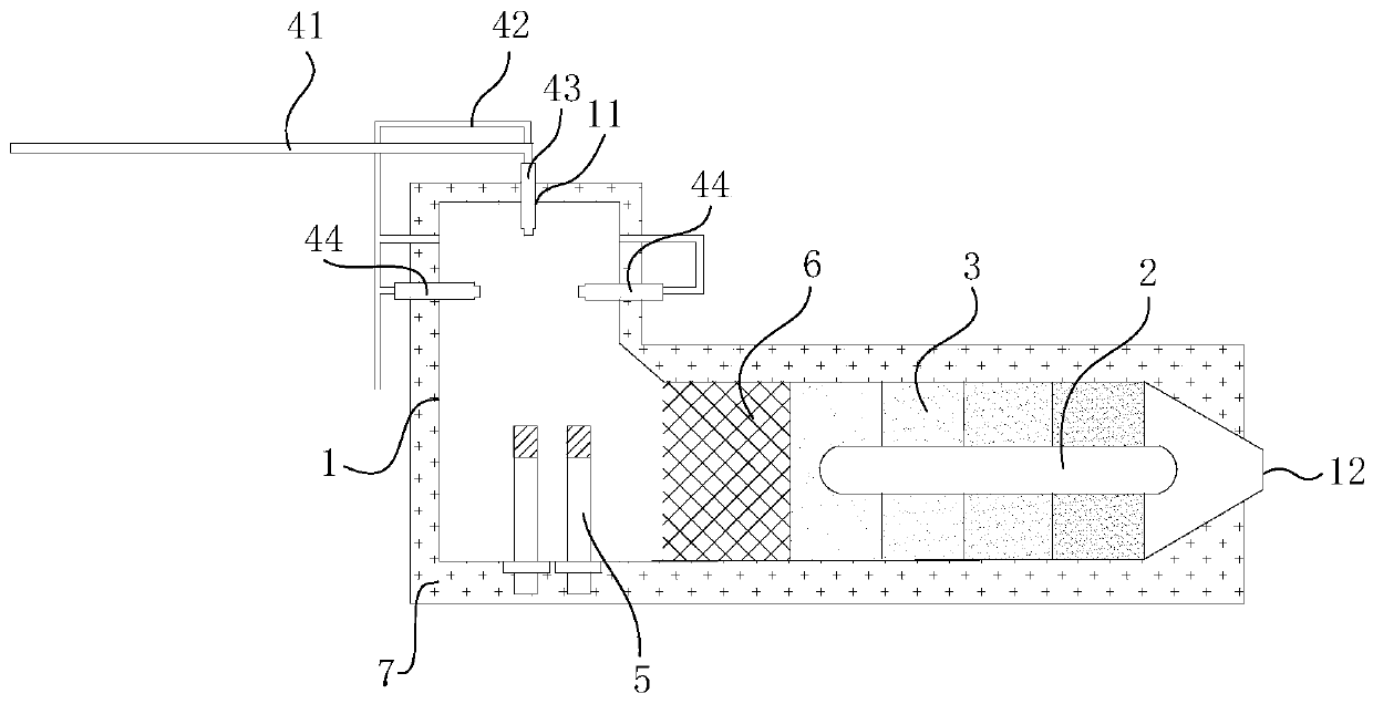
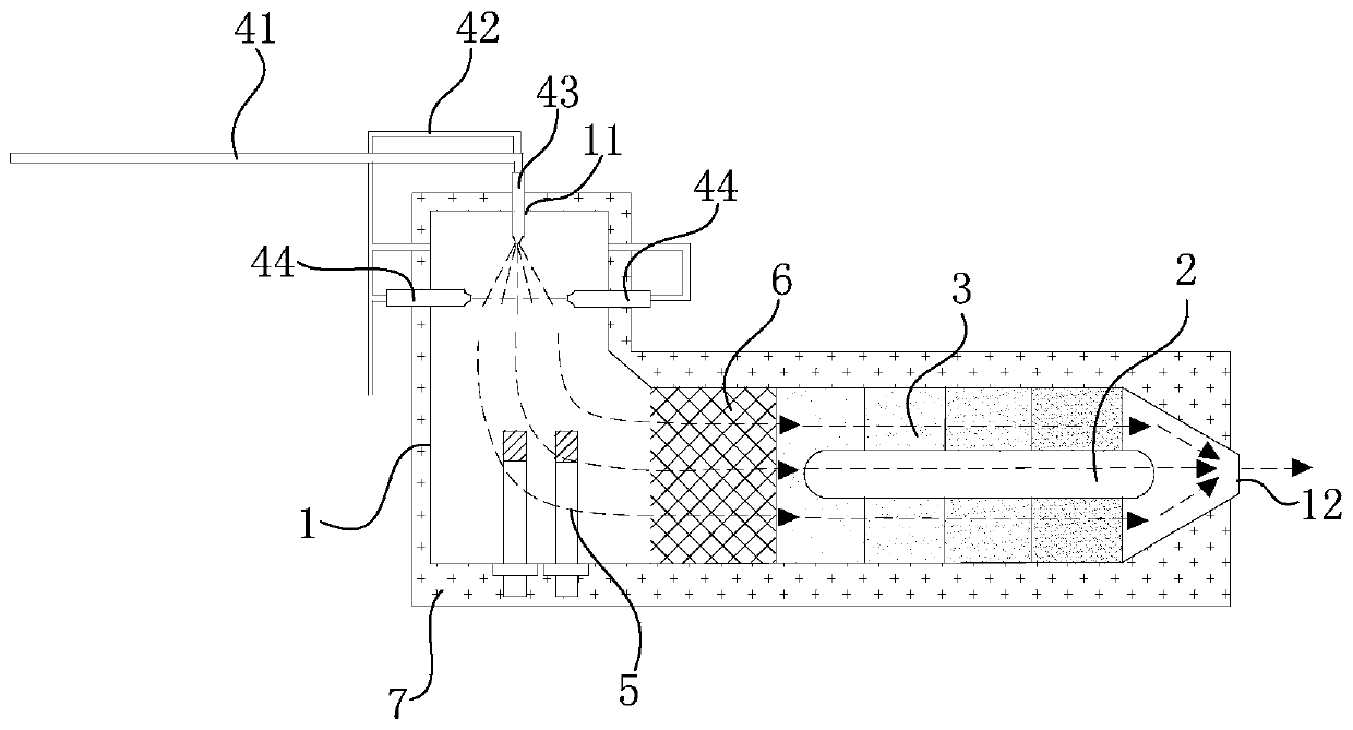
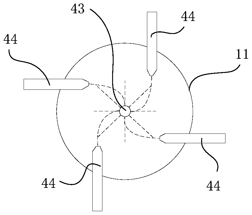
[0041] refer to figure 1 , figure 2 and image 3 , this embodiment provides a liquid fuel catalytic reforming device, the liquid fuel catalytic reforming device includes a housing 1 and a high-temperature heat pipe 2; a reaction chamber is provided inside the housing 1, and the inside of the reaction chamber includes a catalytic reforming area, the catalytic reforming area is used to fill the catalyst 3; on the housing 1, the two ends of the catalytic reforming area are respectively provided with a reaction chamber inlet 11 and a reaction chamber outlet 12; the high temperature heat pipe 2 is configured to be able to be assembled in the catalytic reforming area The inside of the region is used to balance the temperature of the catalyst 3 filled in the catalytic reforming region along the direction of fluid flow from the reaction chamber inlet 11 to the reaction chamber outlet 12 .

[0042] Among them, the heat pipe is a kind of heat transfer device with excellent thermal co...

Embodiment 2

[0061] refer to Figure 4 and Figure 5 , the present embodiment provides another liquid fuel catalytic reforming device, the liquid fuel catalytic reforming device includes a housing and a high-temperature heat pipe 2; the housing includes an inner housing 101 and an outer housing 102, and the interior of the inner housing 101 is arranged There is a first reaction chamber, and a second reaction chamber is arranged inside the outer casing 102. The inside of the first reaction chamber includes a catalytic reforming area, and the catalytic reforming area is used to fill the catalyst 3; A first reaction chamber inlet 1011 and a first reaction chamber outlet 1012 are respectively provided at both ends of the entire region, and the high-temperature heat pipe 2 is configured to be able to be assembled inside the catalytic reforming region to balance the catalyst filled inside the catalytic reforming region 3 the temperature along the direction extending from the first reaction cham...


PUM


Abstract

The invention provides a liquid fuel catalytic reforming device, and relates to the technical field of hydrogen production devices. The liquid fuel catalytic reforming device comprises a shell body and a high-temperature hot pipe; a reaction cavity is formed in the shell body, the inner part of the reaction cavity comprises a catalytic reforming area, and the catalytic reforming area is used for filling a catalyst; a reaction cavity inlet and a reaction cavity outlet are correspondingly formed in the parts, located at the two ends of the catalytic reforming area, of the shell body; and the high-temperature hot pipe is configured to be capable of being assembled in the inner part of the catalytic reforming area to balance the temperature of the catalyst filled in the inner part of the catalytic reforming area in the direction of flowing from the reaction cavity inlet to the reaction cavity outlet of fluid. According to the liquid fuel catalytic reforming device, the technical problems of 'overheating' or 'supercooling' of a catalyst bed layer and large internal temperature gradient in the process of liquid fuel reforming in the prior art are at least alleviated.

Description

technical field [0001] The invention relates to the technical field of hydrogen production devices, in particular to a liquid fuel catalytic reforming device. Background technique [0002] Fuel cell is a new type of energy supply technology, which has the advantages of high efficiency, up to 60%, low noise, almost no pollution emission, etc. It is suitable for automobile power supply, portable power supply, distributed energy system, household combined heat and power supply It is a crucial technology in the "hydrogen economy" system. However, there are still bottlenecks in key technologies such as hydrogen production, storage and transportation, which limits the large-scale promotion of fuel cell technology and the development of mobile and miniaturized hydrogen production devices based on the reforming and conversion of liquid fuels such as gasoline and diesel. And technology is an important way to solve the above problems. [0003] Liquid fuels represented by gasoline an...

Claims


Application Information

Patent Timeline
Patent Type & Authority Applications(China)
IPC IPC(8): C01B3/38
CPCC01B3/38C01B2203/0227C01B2203/0233
Inventor 史翊翔史继鑫曾洪瑜蔡宁生
Owner TSINGHUA UNIV
Why Eureka
Try Eureka