
Ultrasound imaging guidewire with static central core and tip

a technology of ultrasonic imaging and guidewires, applied in the field of ultrasonic imaging guidewires, can solve the problems of increasing difficulty and time required for guidewire placement, time-consuming and difficult task of placement of guidewires, and increasing difficulty in placing guidewires

Inactive Publication Date: 2006-06-13
BOSTON SCI CORP
View PDF33 Cites 58 Cited by
  • Summary
  • Abstract
  • Description
  • Claims
  • Application Information

AI Technical Summary

Benefits of technology

[0009]Accordingly, a general object of the present invention is to provide an apparatus and method for permitting multi-position, ultrasonic imaging without losing correct guidewire positioning.
[0010]A further object of this invention is to provide a faster imaging guidewire procedure, and to eliminate the complexity associated with the ultrasonic imaging guidewire procedure.
[0011]Another object of this invention is to prevent harm to a patient's vessels by eliminating the back and forth movement of the guidewire tip.

Problems solved by technology

Such placement may require a considerable amount of time.
Furthermore, the difficulty and time required for guidewire placement increases with increasing vessel occlusion at later stages of disease.
Thus, placement of the guidewire can be a time-consuming and difficult task.
The problem with advancements and pullbacks of the imaging guidewire is that the physician may lose the correct placement of the guidewire, and have to spend additional time repositioning the guidewire.
Furthermore, the back-and-forth movement of the guidewire may damage the patient's vessels.
A significant problem encountered by physicians is the proper positioning of stents.
It is often extremely difficult for a physician to accurately determine the correct location to deploy a stent, particularly at a bifurcating vessel.
This is particularly dangerous if the vessel 102 becomes diseased, such as at 104, and access is needed for therapy.

Method used


Image

  • Ultrasound imaging guidewire with static central core and tip
  • Ultrasound imaging guidewire with static central core and tip
  • Ultrasound imaging guidewire with static central core and tip

Examples


Embodiment Construction

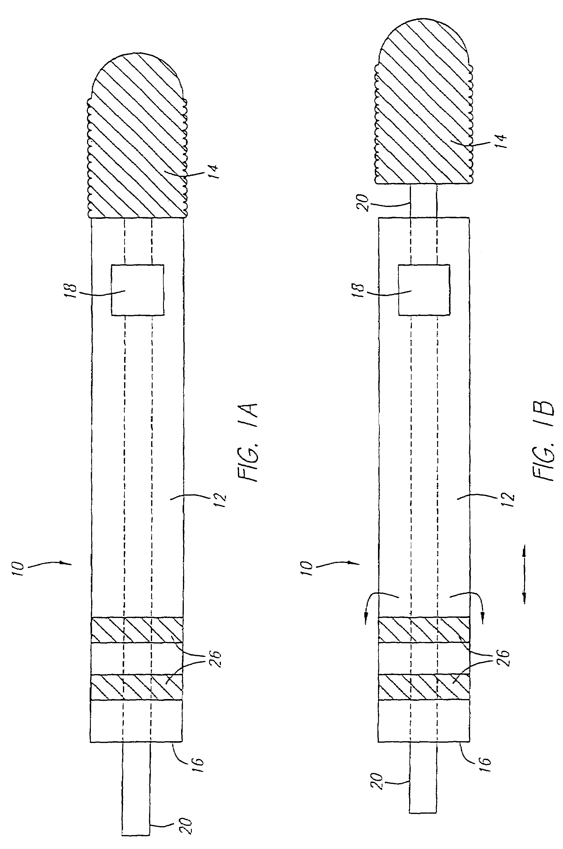
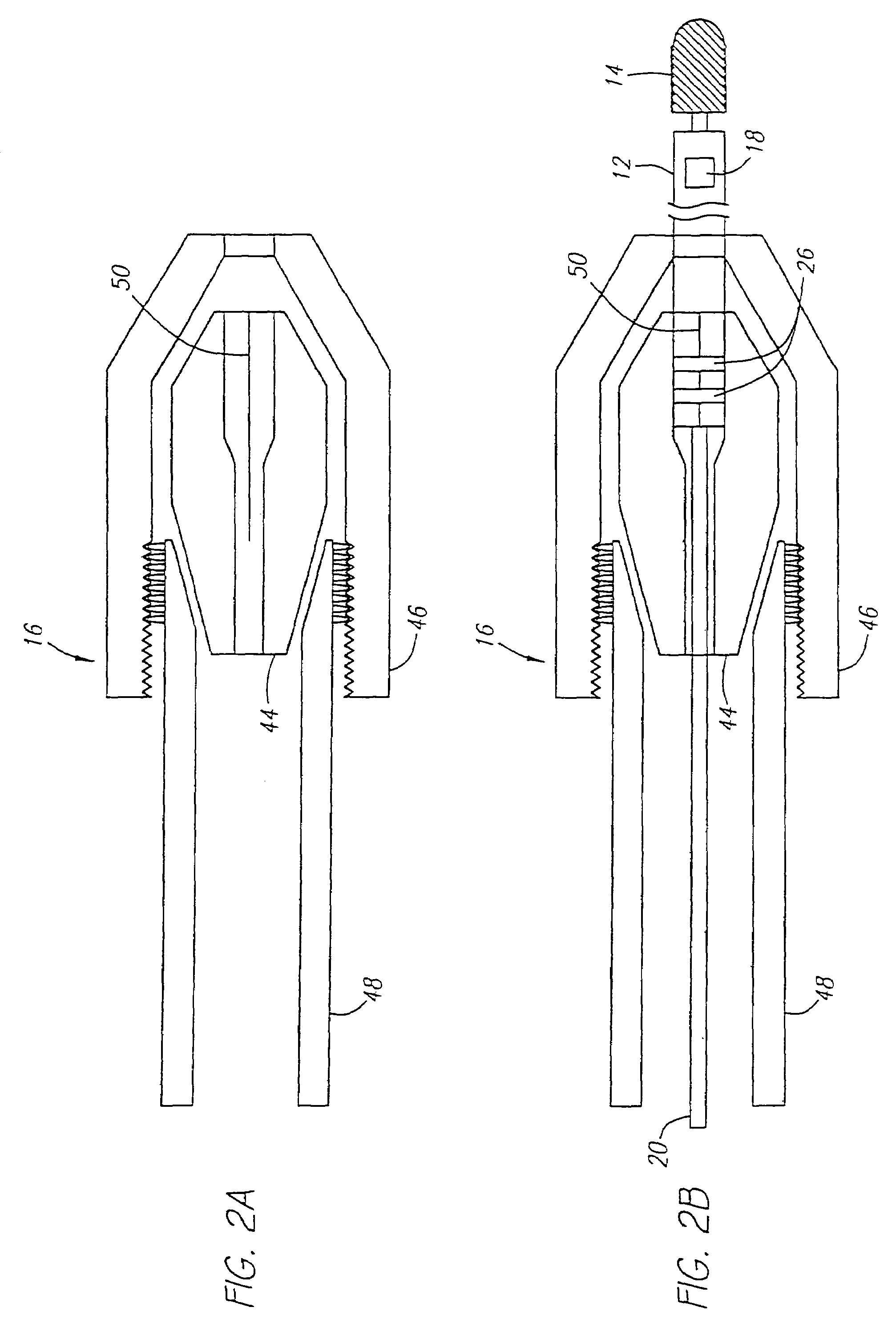
[0024]Referring to FIGS. 1 and 2, the present invention is directed to an ultrasound imaging guidewire 10. The guidewire 10 must have sufficient pushability and torque transmission ability to traverse a tortuous anatomy of blood vessels. Pushability means the characteristics of the guidewire 10 that can reliably transmit a pushing force given by the operator at the proximal end of the guidewire to the distal end thereof. Torque transmission ability means the characteristics that can reliably transmit rotational force applied to the proximal end of the guidewire to the distal end thereof. The imaging guidewire body 12 exhibits uniform, suitable axial and lateral stiffness and torquability up to a desired distal region, where the stiffness gradually changes to a floppy tip 14. The guidewire enables predictable torquing and pushability from proximal regions to the distal floppy tip 14 as is required for proper functioning as a guidewire.

[0025]Ultrasound imaging guidewire 10 includes an...


PUM


Abstract

An ultrasound imaging guidewire, that is inserted into a patient's body. The guidewire has a static central core and an imaging guidewire body comprising an acoustical scanning device. The acoustical scanning device can be rotated to obtain 360 degree acoustical images of a site of interest in the patients body. Furthermore, the imaging guidewire includes a connector that permits the imaging guidewire body to be disengaged from the static central core tip so that the imaging guidewire body can be axially translated to obtain multi-position imaging. The imaging guidewire body is axially translated without losing the original guidewire positioning because the static central core maintains its position in the patient's body.

Description

CROSS-REFERENCE TO RELATED APPLICATIONS[0001]This application is a continuation of U.S. patent application Ser. No. 10 / 405,586, now U.S. Pat. No. 6,770,035, filed on Apr. 1, 2003, which is a continuation of Ser. No. 09 / 844,644, now U.S. Pat. No. 6,585,654, filed on Apr. 27, 2001, which is a continuation of Ser. No. 09 / 625,168 now U.S. Pat. No. 6,248,076, filed on Jul. 25, 2000, which is a continuation of Ser. No. 09 / 393,507, now U.S. Pat. No. 6,171,250, filed on Sep. 10, 1999, which is a continuation of Ser. No. 08 / 939,867, now U.S. Pat. No. 5,951,480, filed on Sep. 29, 1997.FIELD OF THE INVENTION[0002]This invention relates to medical guidewires typically used by physicians to gain access to restricted regions of the body and over which therapeutic devices are passed for insertion to a site of interest. Specifically, the invention relates to an ultrasound imaging guidewire with a detachable imaging guidewire body and a stationary central core.BACKGROUND OF THE INVENTION[0003]Many s...

Claims


Application Information

Patent Timeline
IPC IPC(8): A61B8/14A61B8/12A61M25/09
CPCA61B8/12A61B8/4461A61B8/4209A61M25/09
Inventor WHITE, DAVID A.BELEF, W. MARTIN
Owner BOSTON SCI CORP
Learn More