
Catalytic reforming energy-saving system, catalytic reforming energy-saving method and catalytic reforming reaction system

A catalytic reforming, energy-saving system technology, applied in the direction of naphtha catalytic reforming, reforming operation control/regulation, petroleum industry, etc. Low temperature and other problems, to achieve the effect of lowering temperature, reducing cooling load, and reducing energy supply

Inactive Publication Date: 2020-02-11
CHINA PETROLEUM & CHEM CORP +1
View PDF3 Cites 2 Cited by
  • Summary
  • Abstract
  • Description
  • Claims
  • Application Information

AI Technical Summary

Problems solved by technology

[0004] The temperature of the oil gas at the top of the pre-fractionation tower of the above-mentioned reforming unit is relatively high, and it needs to be condensed and cooled by the air cooler and water cooler before being used as the top reflux and feed to the n-isopentane separation tower, and the low-temperature heat is not recovered; The low-temperature heat source of the reformed product after heat exchange is abundant; the liquid-phase cooling capacity at the bottom of the high-pressure absorption tank is not fully utilized, and it directly exchanges heat with the bottom oil of the reformed oil stabilization tower, the heat exchange temperature difference is large, and the reformed oil stabilization tower enters Material temperature is low

Method used


Image

  • Catalytic reforming energy-saving system, catalytic reforming energy-saving method and catalytic reforming reaction system
  • Catalytic reforming energy-saving system, catalytic reforming energy-saving method and catalytic reforming reaction system
  • Catalytic reforming energy-saving system, catalytic reforming energy-saving method and catalytic reforming reaction system

Examples


Embodiment 1

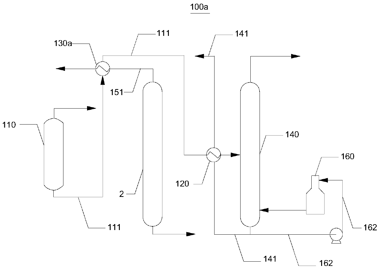
[0036] like figure 1 As shown, the catalytic reforming energy-saving system 100a provided in this embodiment includes a high-pressure absorption tank 110 , a reformed oil stabilization tower 140 and a first heat exchanger 120 .

[0037] Specifically, the high-pressure absorption tank 110 is connected with a bottom liquid output pipe 111, and the reformed oil stabilization tower 140 is connected with a bottom oil output pipe 141, and the bottom oil output pipe 141 communicates with the heat flow channel of the first heat exchanger 120 as a heat source pipeline, The bottom liquid output pipe 111 communicates with the cold flow channel of the first heat exchanger 120 as a cold source pipe, and the bottom liquid output pipe 111 communicates with the feed port of the reformed product oil stabilization tower 140 for transporting the bottom liquid to the reformed product. Oil stabilization tower.

[0038] Most of the gas at the top of the low-pressure gas-liquid separation tank ente...

Embodiment 1-1

[0048] This embodiment is implemented by using the catalytic reforming energy-saving system 100a provided in Embodiment 1 as a reforming energy utilization device.

[0049] Taking the 700,000-ton / year continuous reforming unit of a refinery as an example, the technology and method of energy saving and consumption reduction of this unit are explained. This device adopts the first-generation patented technology of IFP in France, and is aimed at producing high-octane gasoline components, and provides raw materials for aromatics complexes.

[0050] like figure 1 As shown, a kind of catalytic reforming energy-saving method described in this embodiment is specifically:

[0051] The tank bottom liquid (40°C) from the high-pressure absorption tank 110 and the oil gas at the top of the pre-fractionation tower 2 are heat-exchanged to 65°C through the newly added second heat exchanger 130a, and then heat-exchanged to 175°C through the first heat exchanger 120 After entering the reforme...

Embodiment 2

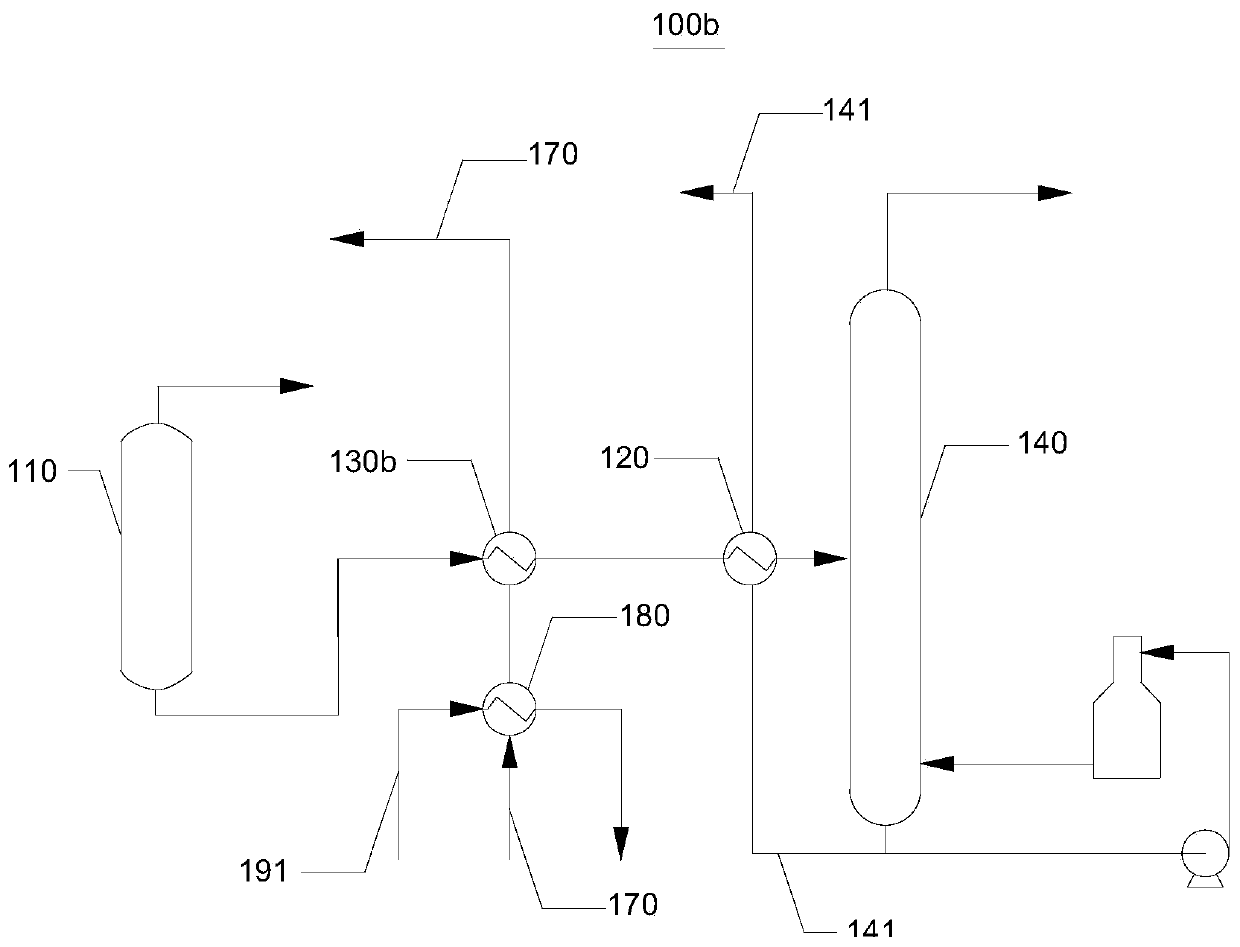
[0053] like figure 2 As shown, the catalytic reforming energy-saving system 100b provided by the embodiment of the present invention has the same realization principle and technical effect as that of Embodiment 1. For a brief description, the details not mentioned in this embodiment can be referred to in Embodiment 1. Corresponding content.

[0054] The catalytic reforming energy-saving system 100b provided in this embodiment includes a second heat exchanger 130b and a reformed product output pipe 170 communicated with the reforming reaction unit of the catalytic reforming reaction system. The reformed product output pipe 170 is used as a heat source pipe to connect with the second The heat flow channel of the second heat exchanger 130a is connected, and the bottom liquid output pipe 111 is connected with the cold flow channel of the second heat exchanger 130b as a cold source pipe.

[0055] The bottom liquid and the reformed product exchange heat, the temperature of the bot...


PUM


Abstract

The invention relates to the technical field of catalytic reforming, and discloses a catalytic reforming energy-saving system, a catalytic reforming energy-saving method and a catalytic reforming reaction system. The catalytic reforming energy-saving system comprises a high-pressure absorption tank, a reformed oil stabilizing tower and a first heat exchanger, wherein the high-pressure absorption tank is communicated with a base solution output pipe; the base solution output pipe is communicated with the feed port of a reformate stabilizing tower; the reformate stabilizing tower is communicatedwith a base oil output pipe; the base oil output pipe serves as a heat source pipeline; and the base solution output pipe serves as a cold source pipeline and is connected with the first heat exchanger. The catalytic reforming energy-saving method comprises a step of performing heat exchange on a base solution generated by the high-pressure absorption tank with base oil generated by the reformatestabilizing tower as a heat source. The catalytic reforming reaction system comprises the catalytic reforming energy-saving system. According to the catalytic reforming energy-saving system, the catalytic reforming energy-saving method and the catalytic reforming reaction system, system load can be reduced, system energy consumption is reduced, and resource conservation is achieved.

Description

technical field [0001] The invention relates to the technical field of catalytic reforming, in particular to a catalytic reforming energy-saving system, an energy-saving method and a catalytic reforming reaction system. Background technique [0002] As the reforming unit of the naphtha processing unit, it mainly uses naphtha as the raw material to produce reformed oil rich in aromatics, which is used as the raw material of aromatics and gasoline blending components, and at the same time rich in hydrogen and a small amount of liquefied gas. Generally, it mainly consists of three units: raw material pretreatment, reforming reaction and catalyst regeneration. Among them, the pretreatment unit includes three parts: pre-fractionation, pre-hydrogenation and stripping. The naphtha raw material from the naphtha stabilization system enters the pre-fractionation tower for fractionation. 1. After being condensed and cooled by the water cooler, part of it is used as tower top reflux, a...

Claims


Application Information

Patent Timeline
IPC IPC(8): C10G35/04C10G35/24C10G61/00
CPCC10G35/04C10G35/24C10G61/00C10G2300/1037C10G2300/1044
Inventor 孙欢欢经铁崔新安王洪彬郭荣群王雪于珊珊
Owner CHINA PETROLEUM & CHEM CORP
Learn More