Over-temperature alarm circuit for transformer

A technology of alarm circuit and transformer, applied in the field of transformer circuit

Inactive Publication Date: 2020-01-31
徐州柏兴电子有限公司
View PDF6 Cites 0 Cited by
  • Summary
  • Abstract
  • Description
  • Claims
  • Application Information

AI Technical Summary

Problems solved by technology

[0004] In view of the problems existing in the above-mentioned prior art, the present invention provides an over-temperature alarm circuit for a transformer, which can monitor a working environment of the transformer in real time, but when working in a high-temperature environment, it can remind the staff that the temperature of the transformer is too high and needs to be Perform cooling treatment to prevent the transformer from being easily damaged due to long-term high temperature environment

Method used


Image

  • Over-temperature alarm circuit for transformer

Examples


Embodiment Construction

[0013] The present invention will be further described below in conjunction with accompanying drawing.

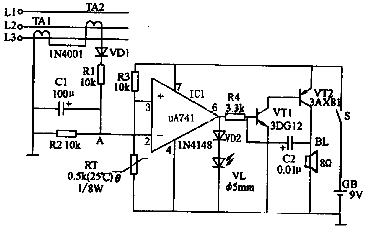
[0014] Such as figure 1 As shown, an over-temperature alarm circuit for transformers, including current transformer TA1, current transformer TA2, thermistor RT, diodes VD1~VD2, resistors R1~R4, capacitor C1, electrolytic capacitor C2, operational amplifier IC1 , transistor VT1, transistor VT2, speaker BL, light-emitting diode VL, switch S, battery GB,

[0015] The current transformer TA1 and the current transformer TA2 are connected to the two-phase line on the secondary side of the transformer. One end of the current transformer TA1 is connected in series with the current transformer TA2 and then connected to the positive pole of the diode VD1, and the negative pole of the diode VD1 is connected to one end of the resistor R1. , the other end of the resistor R1 is respectively connected to the positive pole of the capacitor C1, one end of the resistor R2, and pin 2 of the ...


PUM


Abstract

An over-temperature alarm circuit for a transformer comprises a current transformer TA1, a current transformer TA2, a thermistor RT, diodes VD1 to VD2, resistors R1 to R4, a capacitor C1, an electrolytic capacitor C2, an operational amplifier IC1, a transistor VT1, a transistor VT2, a loudspeaker BL, a light emitting diode VL, a switch S and a battery GB. The over-temperature alarm circuit can monitor a working environment of the transformer in real time, and when the transformer works in a high temperature environment, the circuit can remind staff that the transformer is at a too high temperature and needs to be cooled, thereby preventing the problem that the transformer is easily damaged due to being in the high temperature environment for a long term.

Description

technical field [0001] The invention relates to a transformer circuit, in particular to an over-temperature alarm circuit for a transformer, and belongs to the technical field of transformer equipment. Background technique [0002] The transformer is a device that uses the principle of electromagnetic induction to change the AC voltage. The main components are the primary coil, the secondary coil and the iron core (magnetic core). The main functions are: voltage transformation, current transformation, impedance transformation, isolation, voltage stabilization (magnetic saturation transformer), etc. According to the use, it can be divided into: power transformers and special transformers (electric furnace transformers, rectifier transformers, power frequency test transformers, voltage regulators, mining transformers, audio transformers, intermediate frequency transformers, high frequency transformers, impact transformers, instrument transformers, electronic transformers , re...

Claims


Application Information

Patent Timeline
Patent Type & Authority Applications(China)
IPC IPC(8): G08B21/24G01R31/00G01K1/02G01K7/22
CPCG08B21/24G01R31/00G01K1/024G01K7/22
Inventor 周硕
Owner 徐州柏兴电子有限公司
Why Eureka
Try Eureka