
A magnetorheological fluid flexible clamping device and method for blade parts

A magnetorheological fluid and flexible clamping technology, applied in the field of parts clamping, can solve problems such as affecting machining accuracy, blade fatigue strength drop, blade fracture, etc., to ensure support reliability, machining accuracy, and support rigidity. Effect

Active Publication Date: 2020-09-29
DALIAN UNIV OF TECH
View PDF10 Cites 0 Cited by
  • Summary
  • Abstract
  • Description
  • Claims
  • Application Information

AI Technical Summary

Problems solved by technology

However, there are some problems with this method: first, the low-melting-point alloy vapor is toxic, which affects health and pollutes the environment; second, the bismuth element in the low-melting-point alloy penetrates into the blade, resulting in a decrease in the fatigue strength of the blade, which easily induces blade fracture; third, the cast alloy The blade needs to be removed before pouring, and the fixture needs to be clamped twice with the workbench after pouring, resulting in positioning error and affecting the machining accuracy
[0004] In 2015, Zhang Dinghua et al. invented a flexible support device in the patent CN201510046697.0. The lower part of the blade body is immersed in the magnetorheological fluid, and the flexible support is implemented through external excitation, which can meet the clamping requirements during the processing of the upper part of the blade body. Requirements are met, but follow-up cleaning is required

Method used


Image

  • A magnetorheological fluid flexible clamping device and method for blade parts
  • A magnetorheological fluid flexible clamping device and method for blade parts
  • A magnetorheological fluid flexible clamping device and method for blade parts

Examples


Embodiment Construction

[0016] The embodiments of the present invention will be described in detail in conjunction with the drawings and technical solutions.

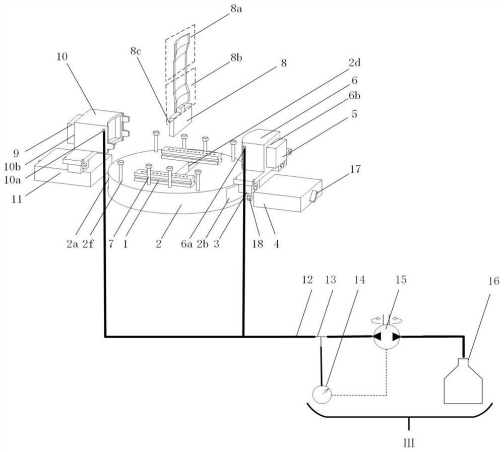
[0017] The blade 8 is a high-temperature alloy GH4196 sheet material, the thickness after rolling is 0.8mm, the total length of the blade is 150mm, the final surface roughness is 0.4, and the minimum work difference of the airfoil profile is +0.03~-0.03mm. Carbonyl iron powder magnetorheological fluid is made of 40% volume fraction of carbonyl iron powder and 60% volume fraction of silicone oil, with a density of 3.55g / ml. The maximum thickness of magnetorheological fluid is 14mm. Grinding force 100N. The magnetic field strength is greater than 120A / m.

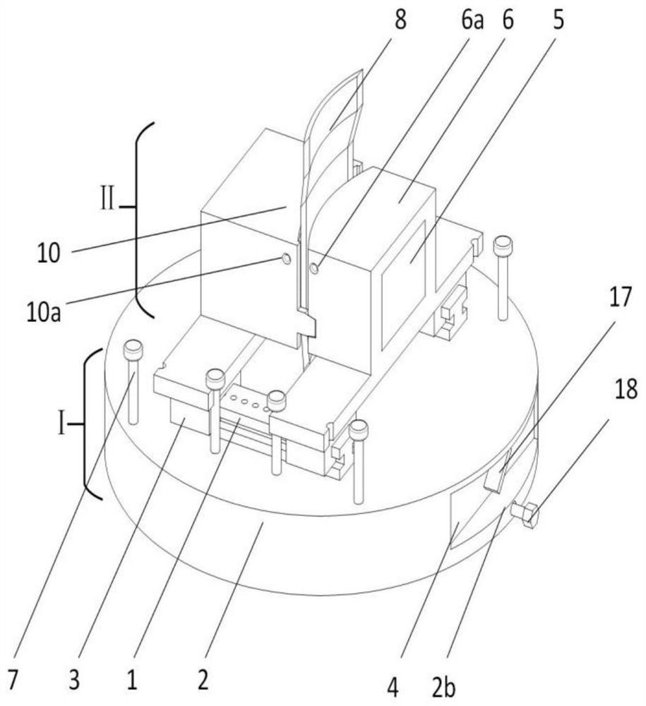
[0018] attached figure 1 It is the overall schematic diagram of the magnetorheological fluid flexible clamping device for processing blade parts. The magnetorheological flexible clamping device in the figure is composed of tenon magnetorheological clamping mechanism Ⅰ, blade body magnetorhe...


PUM


Abstract

The invention discloses a blade part magnetorheological fluid flexible clamping device and method, belongs to the technical field of part clamping, and relates to the blade part magnetorheological fluid flexible clamping device and method. The clamping device consists of a tenon magnetorheological fluid clamping mechanism, a blade body magnetorheological fluid clamping mechanism and a magnetorheological fluid filling device; the blade body magnetorheological clamping mechanism is connected with the upper portion of the tenon magnetorheological clamping mechanism through bolts; and a female diefilling port and a male die filling port in the blade body magnetorheological clamping mechanism are respectively connected with a channel in the magnetorheological fluid filling device. In the clamping method, a blade is firstly placed in a base tenon positioning groove, a blade tenon part is clamped by a blade tenon magnetorheological clamping mechanism, and the lower section of the blade is machined. After the lower section of the blade is processed, the lower section of blade body is clamped by the blade body magnetorheological clamping mechanism, and the upper section of the blade is processed. According to the method, under the condition of one-time clamping and positioning, the whole surface of the blade is machined, the integral machining precision is guaranteed, and the method issimple, convenient, rapid and accurate to implement.

Description

technical field [0001] The invention belongs to the technical field of parts clamping, and relates to a magnetorheological fluid flexible clamping device and method for blade parts. Background technique [0002] The blade is an important part of the aviation gas turbine engine, and its reliable clamping is the core link to ensure the efficient removal of material and the geometric accuracy of the final machining of the part. The blade machining process requires reliable blade clamping, and the suspended area should be minimized to prevent vibration deformation. At present, for the processing of blade parts in China, most of them adopt low melting point alloy clamping method. This method reduces the overhang depth of the blade, enhances the stiffness of the upper section of the blade, and reduces the deflection deformation of the blade to ensure the machining accuracy of the blade. However, there are some problems with this method: first, the low-melting-point alloy vapor i...

Claims


Application Information

Patent Timeline
Patent Type & Authority Patents(China)
IPC IPC(8): B23Q3/15B25B11/00
CPCB23Q3/15B25B11/002
Inventor 刘海波王俊鹏李特罗祺单坤牟欣王永青
Owner DALIAN UNIV OF TECH
Learn More