
Random vibration drive ring-down cavity calibration-free gas concentration measurement system and method

A technology of gas concentration measurement and random vibration, which is applied in the direction of measuring device, color/spectral characteristic measurement, and material analysis through optical means, which can solve problems such as fluctuations, simplify experimental operations and measuring devices, simplify system structure, and suppress effect of influence

Active Publication Date: 2020-01-10
BEIHANG UNIV
View PDF7 Cites 10 Cited by
  • Summary
  • Abstract
  • Description
  • Claims
  • Application Information

AI Technical Summary

Problems solved by technology

In view of the above problems, the present invention proposes a random vibration-driven ring-down cavity calibration-free gas concentration measurement system and method, which uses the change of the cavity length to change the frequency selection position of the longitudinal mode of the cavity to realize the time-sharing output of the dual-wavelength attenuation signal, and selects the incident The moment when the light is completely blocked is used as the starting point of the fitted ring-down signal to avoid inaccurate fitting due to fluctuations in light intensity caused by changes in the cavity length, and then use the difference between the two-wavelength exponential attenuation coefficient and the gas concentration Non-linear relationship, realize the anti-vibration and calibration-free concentration measurement of the gas to be measured

Method used


Image

  • Random vibration drive ring-down cavity calibration-free gas concentration measurement system and method
  • Random vibration drive ring-down cavity calibration-free gas concentration measurement system and method
  • Random vibration drive ring-down cavity calibration-free gas concentration measurement system and method

Examples


Embodiment Construction

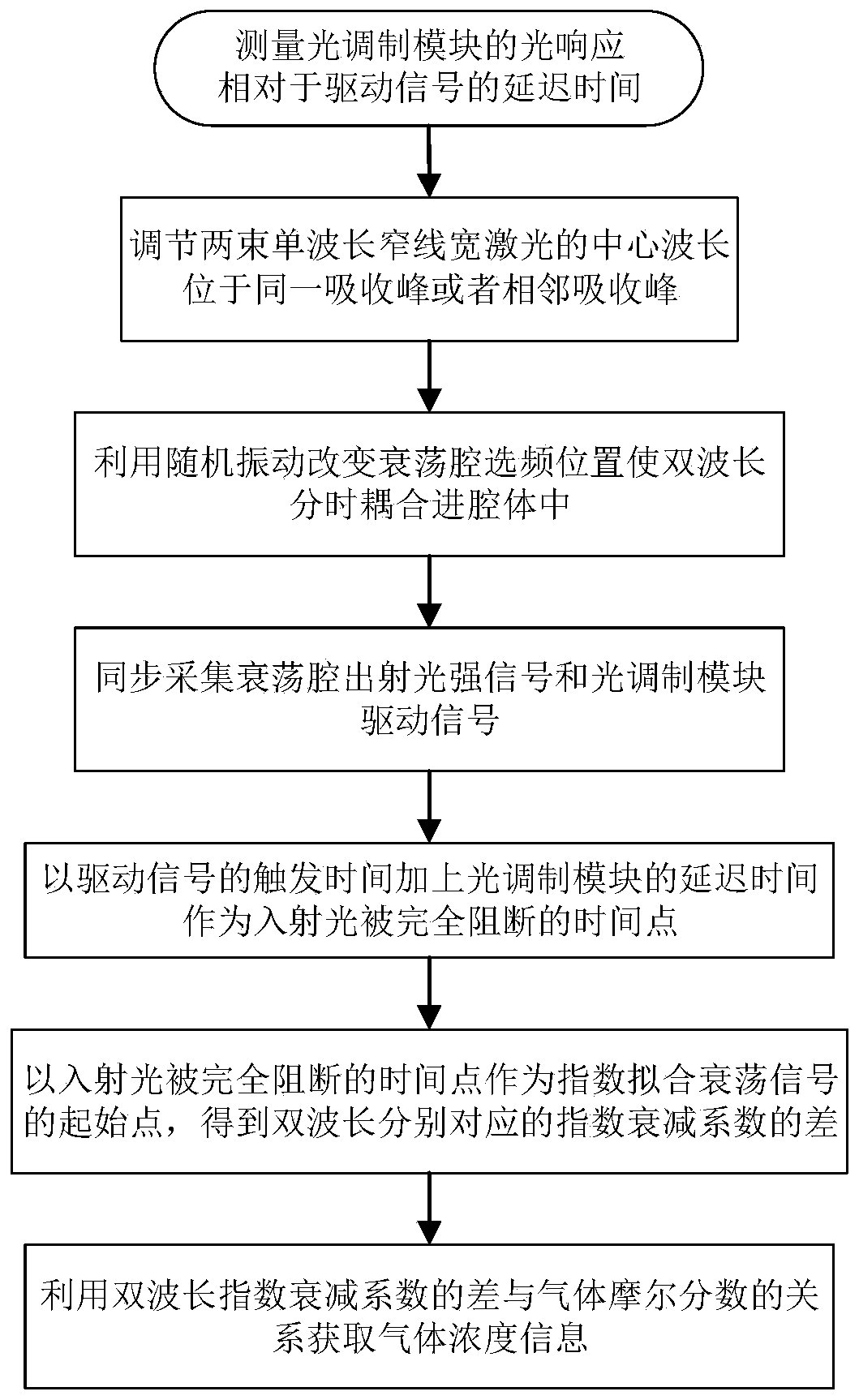
[0023] This paper invents a vibration-resistant and calibration-free gas concentration measurement system and method based on a ring-down cavity. The structure of the system is as follows: figure 2 Among them, the narrow-linewidth laser light source (101) emits two beams of narrow-linewidth laser beams with different wavelengths, which pass into the light modulation module (102) and are periodically turned off, and then incident on a set of high-reflectivity reflectors driven by random vibrations. In the optical ring-down cavity (103) composed of mirrors, the light intensity exponential attenuation signal at the exit end is introduced into the signal acquisition and processing module (104), and finally realizes the random vibration-driven ring-down cavity free of calibration gas concentration measurement.

[0024] Based on the above-mentioned device, the specific implementation of the system is described as follows:

[0025] Step 1: Measure the delay time t of the optical res...


PUM

PropertyMeasurementUnit
Sensitivityaaaaaaaaaa

Abstract

The invention designs a random vibration drive ring-down cavity calibration-free gas concentration measurement system and method. The system comprises a narrow linewidth laser light source, a light modulation module, an optical ring-down cavity and a signal acquisition and processing module. The method comprises the steps: measuring the response delay time of the optical modulation module to a driving signal; adjusting the central wavelengths of the two narrow-linewidth lasers to be located at the same or adjacent absorption peaks, and collecting a light intensity attenuation curve of light emitted by a ring-down cavity filled with gas to be detected; selecting a moment when the incident light is completely blocked as a starting point of a fitting ring-down signal to fit the data to obtainexponential attenuation coefficients corresponding to the dual wavelengths respectively; and finally, obtaining the molar fraction of the gas component by utilizing the relationship between the difference of the dual-wavelength attenuation coefficients and the gas concentration. The dual-wavelength time-sharing frequency-selecting function of the ring-down cavity is achieved through random vibration; the structure is simple, the cost is low, the adaptability to the measurement environment is high, and the dual-wavelength time-sharing frequency-selecting ring-down cavity has a higher use valueand good application prospects in the field of gas detection.

Description

[0001] (1) Technical field [0002] The invention relates to a calibration-free gas concentration measurement system and method driven by random vibrations, and belongs to the technical field of trace gas concentration measurement. [0003] (2) Background technology [0004] The detection of trace gas concentration has important practical application value for human production and life. In an industrial environment, quantitative and accurate real-time monitoring of tiny gas concentrations is an important means of evaluating the degree of chemical reactions, which can avoid accidents by predicting the production stage. In the atmospheric environment, the detection of the concentration of air pollutants can be used to monitor whether the exhaust emissions of enterprises meet the standards, so as to ensure people's health and avoid environmental disasters and ecological environment damage. In the field of biomedicine, the traces of volatile gases such as acetone and propanol in t...

Claims


Application Information

Patent Timeline
Patent Type & Authority Applications(China)
IPC IPC(8): G01N21/39
CPCG01N21/39G01N2021/391
Inventor 徐立军曹章宋振源张宏宇刘怡解恒
Owner BEIHANG UNIV
Learn More