Modular clamping system

A modular, clamping device technology, applied in the direction of clamping, large fixed members, support, etc., can solve the problem that the clamping device is not suitable for applications with high stamping pressure tolerance, and achieve the effect of avoiding lateral force

Active Publication Date: 2020-01-07
SYST 3R INT
View PDF7 Cites 0 Cited by
  • Summary
  • Abstract
  • Description
  • Claims
  • Application Information

AI Technical Summary

Problems solved by technology

[0012] The clamping device disclosed in EP 1 74 1511 is not suitable for applications requiring high resistance to punching forces

Method used


Image

  • Modular clamping system
  • Modular clamping system
  • Modular clamping system

Examples


Embodiment Construction

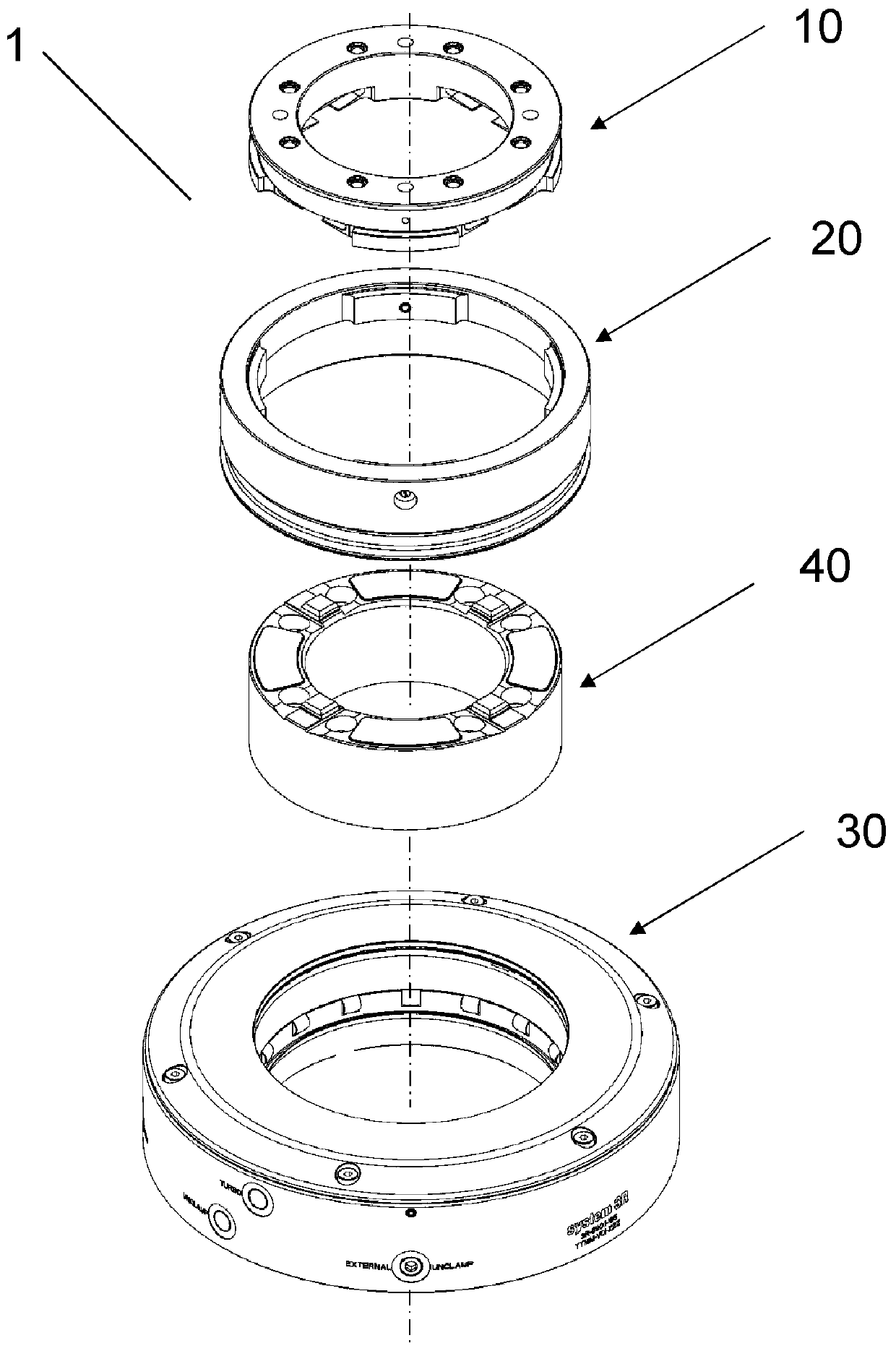
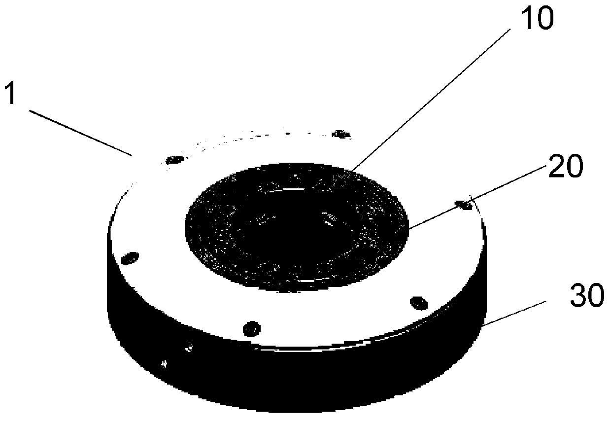
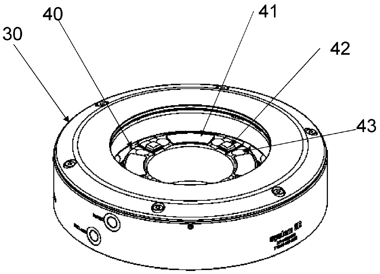
[0039] figure 1 A modular clamping system 1 is shown comprising a bracket 10 , a tubular part 20 , a chuck part 40 and a clamping unit 30 .

[0040] figure 2 The bracket 10 and the tubular portion 20 are shown in an exploded view. The carriage is provided with an x-y reference for positioning in the x-y direction and a z reference in the z direction. In this embodiment, the x-y reference is formed by four pairs of elastic tongues 17 . However, other variants, for example in the form of grooves, are also suitable for the invention. A flat surface 16 on the underside of the bracket forms the z-reference.

[0041] The bracket is mountable into the tubular portion and connected to the tubular portion by a first connection mechanism. exist figure 2 In the embodiment shown in , the bracket is provided with four first bayonet wings 12 for engaging in four corresponding second bayonet wings 22 provided on the tubular portion. The first bayonet wing and the second bayonet wing...


PUM


Abstract

The invention relates to a modular clamping system. The present invention is directed to a modular clamping device for a tool or a workpiece including a pallet having a plurality of x-y references andz references for alignment with a chuck and a clamping unit, which is arranged in the clamped state concentrically at the outside of the chuck. In the clamped state, a tubular part is arranged concentrically between the pallet and clamping unit, and the tubular part is designed such that it is connected to the pallet by a first connecting mechanism and connected to the clamping unit by a second connecting mechanism.

Description

technical field [0001] The invention relates to a clamping device, in particular to a modular clamping device for application in the field of powder metallurgy. Background technique [0002] Modular clamping units are used in particular in powder press applications where the axial pressing forces are very high and at the same time very high demands are placed on positional accuracy. [0003] Presses for powder metallurgy are used for stamping small carbide steel inserts up to sintered larger components such as gears for the automotive industry. The pressure depends on the area of ​​application and is typically 10 tons for small parts and up to 500 tons for large parts. Powder metallurgy presses require a press adapter, which is a unit that can be removed from the press to mount a punching tool. The press adapter is usually equipped with a clamping device for quickly clamping the punching tool, i.e. the upper and lower punches and the die in between. During stamping, a mal...

Claims


Application Information

Patent Timeline
Patent Type & Authority Applications(China)
IPC IPC(8): B22F3/03
CPCB22F3/03B23B31/1071B23B2270/12B23Q1/0063B23Q3/18B30B11/02B30B15/026B23B31/107B23Q1/00B23B31/30B23Q16/10Y10T279/1291Y10T279/17888B23B31/113Y10T279/17752
Inventor J.贝格沃尔H.达尔基斯特J.罗森格伦
Owner SYST 3R INT
Why Eureka
Try Eureka