Drill bit cutting edge grinding device, drill bit cutting edge grinding method and drill bit
A drill and cutting edge technology, applied in the field of drill cutting edge grinding devices, can solve the problems of poor operation convenience and safety, poor operation stability, etc., and achieve the effects of not easily collapsing the cutting edge, not easy to grind and damage, and simplifying the operation steps.
- Summary
- Abstract
- Description
- Claims
- Application Information
AI Technical Summary
Problems solved by technology
Method used
Image
Examples
Embodiment 1
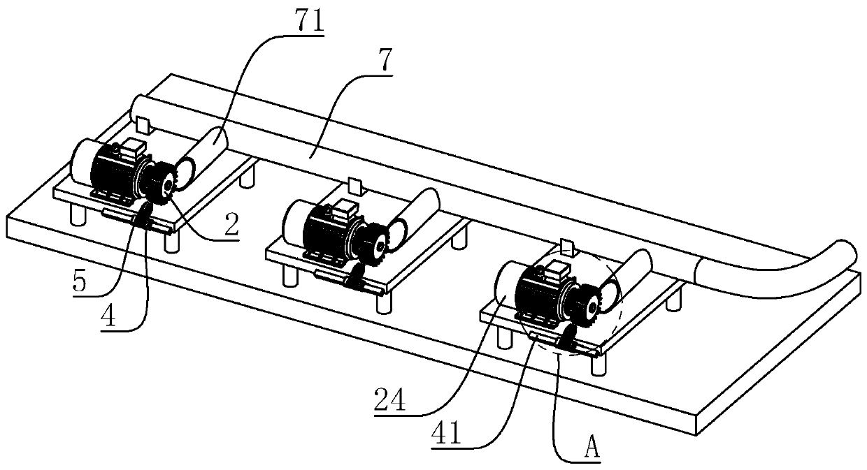
[0045] A kind of drill edge grinding device, with reference to figure 1 , which includes a base 1, the base 1 is in the shape of a square plate, and four corners of the bottom surface are fixed with pads. In this embodiment, the base 1 is arranged in three places in a straight line.
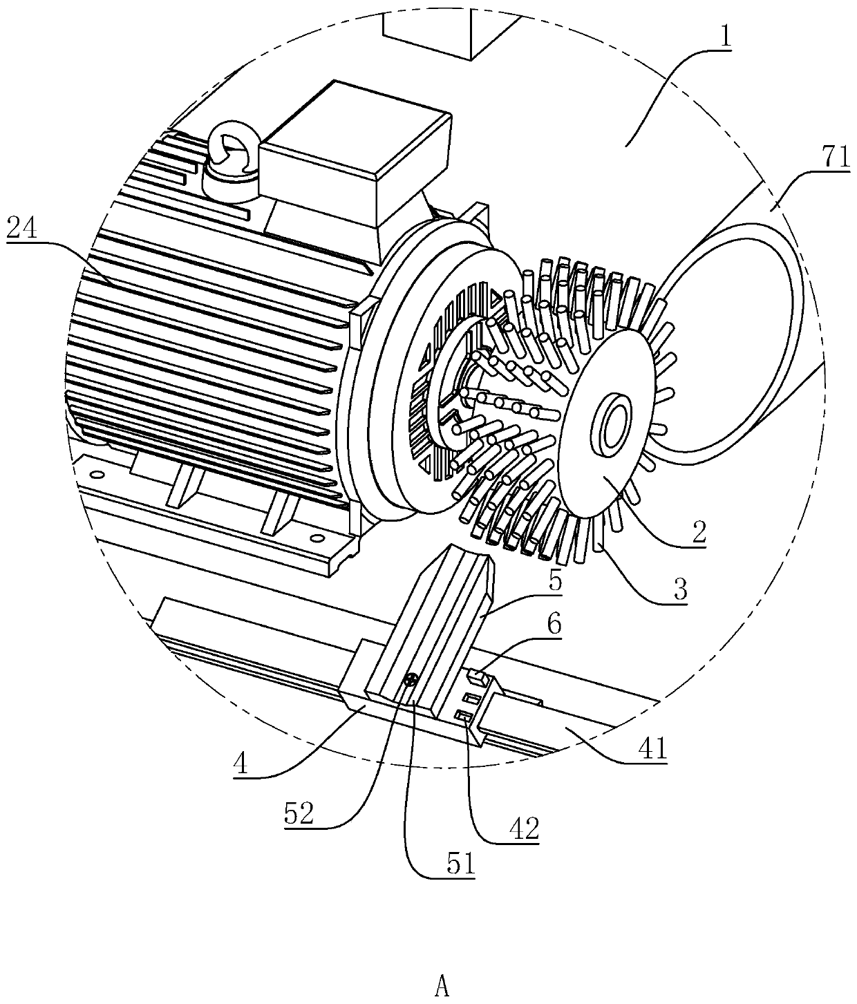
[0046] refer to figure 1 with figure 2 , a servo motor 24 is fixed on each base 1, and a grinding wheel 2 is installed on the driving end of the servo motor 24. The central axis of the grinding wheel 2 is parallel to the base 1 , and the grinding cilia 3 made of high-density polyethylene are evenly distributed on the outer peripheral side wall of the grinding wheel 2 . After the servo motor 24 is energized, it drives the grinding wheel 2 to rotate circumferentially.
[0047] refer to figure 1 with figure 2 One side of the base 1 is provided with a slide rail 41, and the top surface of the slide rail 41 is inclined downward away from the top surface of the base 1, that is, the long side of...
Embodiment 2
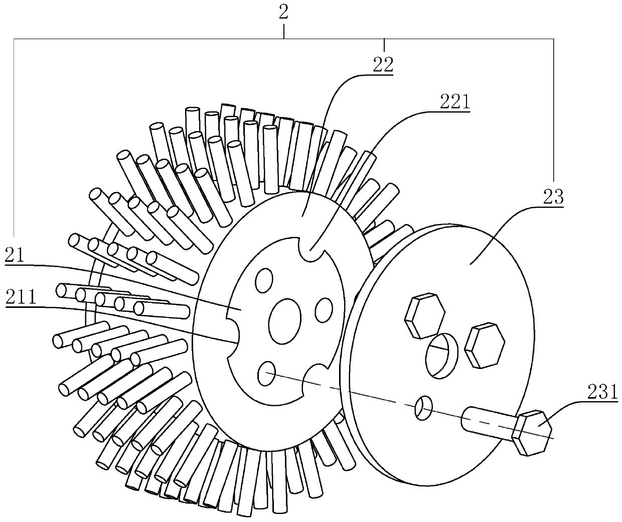
[0053] A kind of drill edge grinding device, with reference to image 3 , based on Embodiment 1, the difference between this embodiment and Embodiment 1 is that the grinding wheel 2 includes a coaxially sleeved wheel body 21 and a ring body 22, and the polishing cilia 3 are evenly distributed on the outer circumferential side wall of the ring body 22 . The inner peripheral sidewall of the ring body 22 is provided with three clamping blocks 221 , and the cross-sectional shape of the clamping blocks 221 is semicircular. The outer peripheral sidewall of the wheel body 21 is provided with a bayonet 211 for the clamping block 221 to snap into, and the end surface of the wheel body 21 is detachably mounted with a fixing plate 23 via a fixing bolt 231 . After the ring body 22 is sheathed on the wheel body 21 so that the clamping block 221 snaps into the bayonet 211 , the fixing plate 23 is attached to the end surface of the wheel body 21 and fixed by the fixing bolt 231 . The ring ...
Embodiment 3
[0055] A method for grinding a drill edge, using the drill edge grinding device of embodiment 1 to grind the edge 82 of the drill 8, specifically comprising the following steps:
[0056] P1, open servo motor 24, make servo motor 24 drive grinding wheel 2 to rotate with the rotating speed of 2800-3200rpm; The rotating speed of grinding wheel 2 can be adjusted according to the actual situation, and the rotating speed of grinding wheel 2 is 2800rpm in the present embodiment;
[0057] P2, clamp the drill bit 8 to be polished in the clamping groove 51 on the clamping block 5, so that the head end of the drill bit 8 faces the grinding wheel 2;
[0058] P3. Press the drill bit 8 to keep the drill bit 8 fixed on the clamping block 5, turn the clamping block 5 until the drill bit 8 deviates from the direction perpendicular to the axis of the grinding wheel 2, maintain the state of the drill bit 8, slide the slider 4 back and forth along the slide rail 41, and make the drill bit The hea...
PUM
 Abstract
Description
Claims
Application Information
 - R&D
- Intellectual Property
- Life Sciences
- Materials
- Tech Scout
- Unparalleled Data Quality
- Higher Quality Content
- 60% Fewer Hallucinations
Browse by: Latest US Patents, China's latest patents, Technical Efficacy Thesaurus, Application Domain, Technology Topic, Popular Technical Reports.
© 2025 PatSnap. All rights reserved.Legal|Privacy policy|Modern Slavery Act Transparency Statement|Sitemap|About US| Contact US: help@patsnap.com


