Optical fiber ring packaging structure

A technology of packaging structure and fiber optic ring, which is applied in the field of fiber optic gyro, to achieve the effects of improving connection strength, improving scale factor stability, and low mechanical stress sensitivity

Pending Publication Date: 2019-11-29
XIAN FLIGHT SELF CONTROL INST OF AVIC
View PDF6 Cites 7 Cited by
  • Summary
  • Abstract
  • Description
  • Claims
  • Application Information

AI Technical Summary

Problems solved by technology

[0005] The purpose of the present invention is to provide a fiber optic ring packaging structure to solve the problem of fiber optic ring packaging under complex environmental conditions in engineering practice, and to improve the environmental adaptability of fiber optic gyroscopes

Method used


Image

  • Optical fiber ring packaging structure
  • Optical fiber ring packaging structure
  • Optical fiber ring packaging structure

Examples


Embodiment Construction

[0029] Below in conjunction with accompanying drawing, the present invention will be further described:

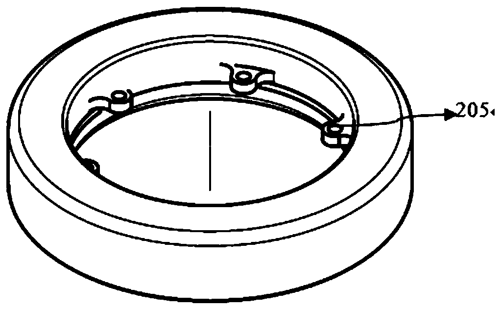
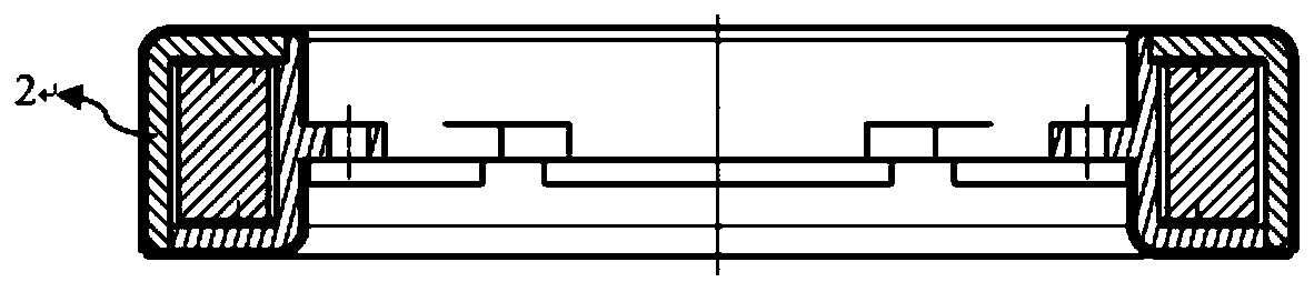
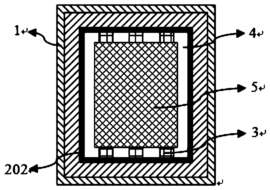
[0030] figure 1 It is the overall structure diagram of the optical fiber ring packaging structure, such as figure 1 As shown, the present invention provides an optical fiber ring packaging structure. figure 2 is a cross-sectional view of the optical fiber ring package structure, image 3 Schematic diagram of the optical fiber ring packaging structure, combined with figure 2 and image 3 As shown, the optical fiber ring packaging structure includes a magnetic shielding layer 1 , a thermal control layer 2 , an adhesive layer 3 , an air gap 4 , and an optical fiber ring 5 . The thermal control layer 2 is a hollow annular body structure, and the optical fiber ring 5 is arranged inside the hollow annular body of the thermal control layer 2. The upper side and the lower side of the optical fiber ring 5 pass through the inner surface of the adhesive layer 3 and the thermal ...


PUM


Abstract

The invention relates to an optical fiber ring packaging structure. The optical fiber ring packaging structure comprises a magnetic shielding layer 1, a thermal control layer 2, bonding layers 3 and an optical fiber ring 5; the optical fiber ring 5 is of an annular body structure; the thermal control layer 2 is of a hollow annular body structure; the optical fiber ring 5 is arranged in the hollowannular body of the thermal control layer 2; the upper side surface and lower side surface of the optical fiber ring 5 are fixedly connected with the inner surface of the thermal control layer 2 through the bonding layers 3; the magnetic shielding layer 1 is of a hollow annular body structure; and the thermal control layer 2 and the optical fiber ring 5 are arranged in the hollow annular body of the magnetic shielding layer 1. With the optical fiber ring packaging structure adopted, an optical fiber ring packaging problem under a complex environmental condition in engineering practice is solved, and the environmental adaptability of an optical fiber gyroscope is improved.

Description

technical field [0001] The invention belongs to the optical fiber gyroscope technology, and in particular relates to an optical fiber ring packaging structure for improving the environmental adaptability of the optical fiber gyroscope. Background technique [0002] As an angle sensor, the fiber optic gyroscope has the advantages of anti-electromagnetic interference, large dynamic range, and high reliability, and is widely used in air, sky, sea, and land fields. However, the fiber optic ring as the core component is extremely sensitive to temperature, magnetic field, vibration, and water vapor. The non-reciprocal phase shift caused by the uncertainty of these environments will cause the zero bias of the fiber optic gyroscope to drift, which limits the further improvement of the performance of the fiber optic gyroscope. [0003] Isolating or weakening the impact of external temperature, magnetic field and vibration environment changes on the fiber optic ring, providing an ide...

Claims


Application Information

Patent Timeline
Patent Type & Authority Applications(China)
IPC IPC(8): G01C19/64G02B7/00
CPCG01C19/64G02B7/008
Inventor 孔军谢良平崔志超寇亮亮谷林宫晓宇
Owner XIAN FLIGHT SELF CONTROL INST OF AVIC
Why Eureka
Try Eureka