
Male connector and connector assembly

Active Publication Date: 2008-12-11
HIROSE ELECTRIC GROUP
View PDF4 Cites 34 Cited by
  • Summary
  • Abstract
  • Description
  • Claims
  • Application Information

AI Technical Summary

Benefits of technology

[0021]Accordingly, it is easy to fit the male connector to the female connector to a specific depth. Further, an influence of a solder shortage in the solder connection surface is minimized. At the same time, the solder barrier layer is not provided on a side edge surface of the connection portion, thereby allowing the solder rising. Accordingly, the solder connection strength is sufficiently obtained in the fillet shape portion.
[0036]Further, the connectors can be low-profiled. Further, there is no solder rising; thereby preventing the solder connection strength from being deteriorated without causing a shortage of solder in the solder connection portion. In addition, the solder rising occurs from the solder connection surface on the side edge surface of the connection portion in which the solder barrier layer is not provided. Accordingly, the fillet shape portion is provided there, thereby ensuring the solder connection strength.

Problems solved by technology

The nickel plated layer has poor solderability property and is not suitable as the solder connection portion of the terminal.

Method used


Image

  • Male connector and connector assembly
  • Male connector and connector assembly
  • Male connector and connector assembly

Examples


Embodiment Construction

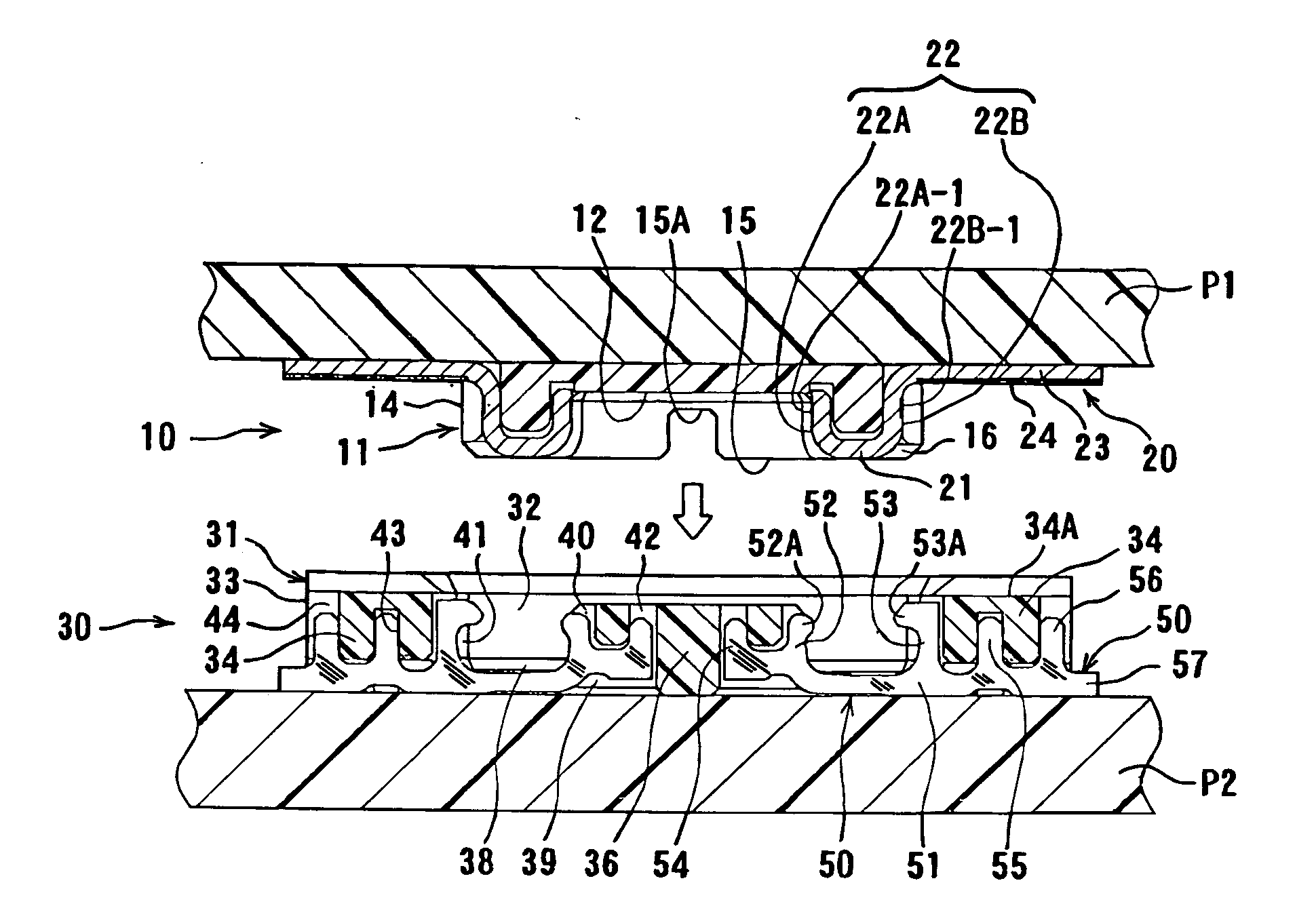
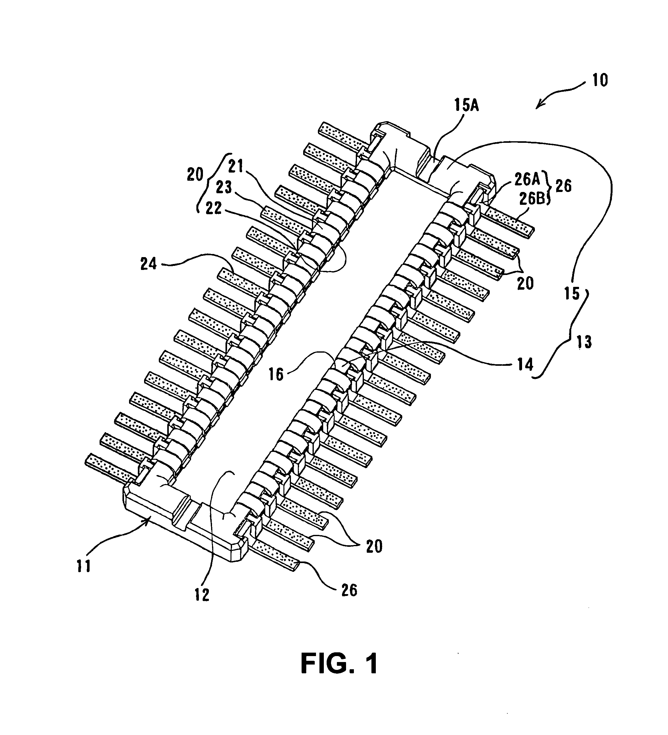
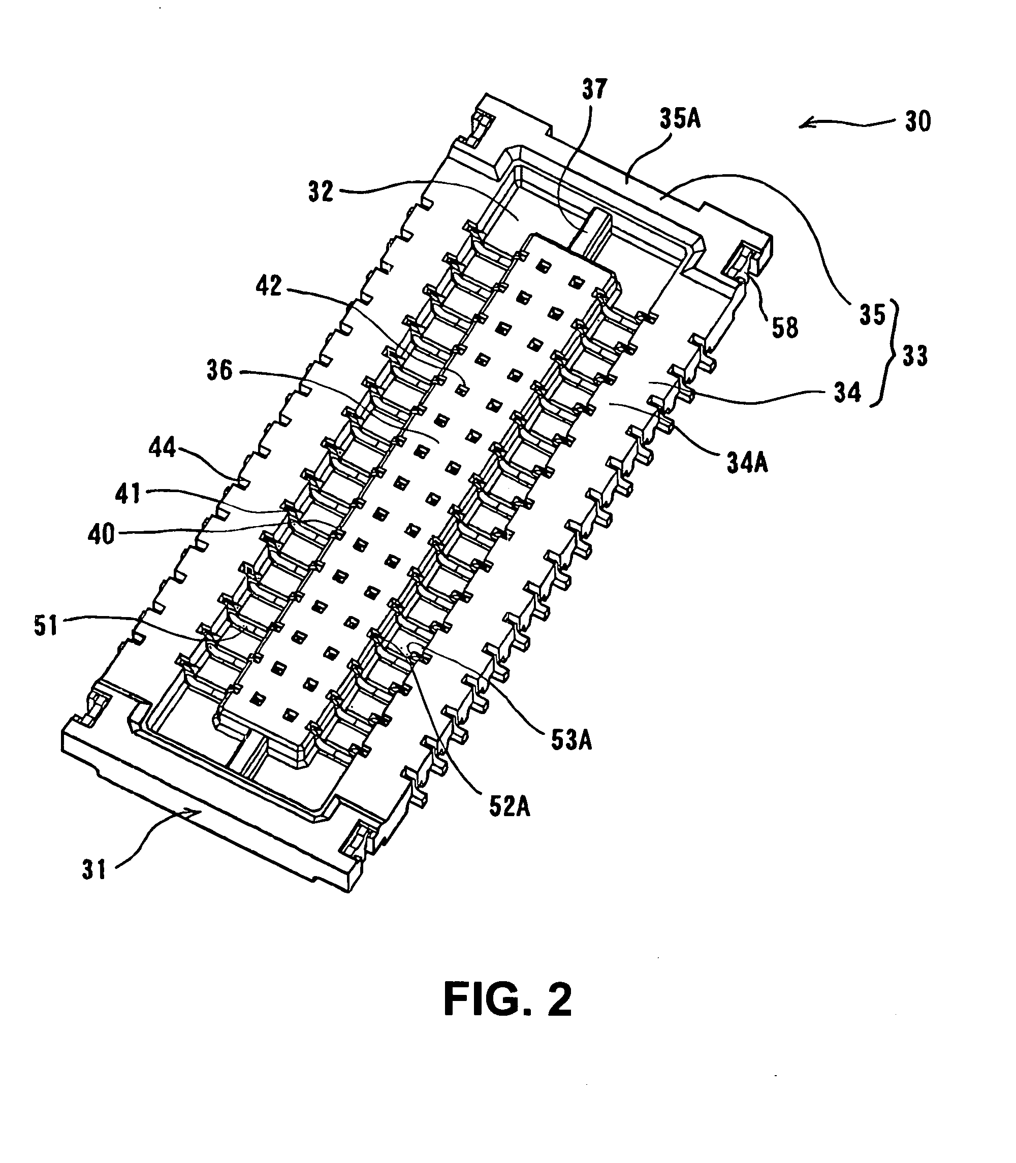
[0045]Hereunder, embodiments of the present invention will be explained with reference to the accompanying drawings.

[0046]In the embodiment, a connector assembly comprises a male connector and a female connector. The male connector and the female connector are fitted with each other to be connected. Each of the male connector and the female connector is attached to a circuit board, so that surfaces of the circuit boards are parallel to each other. Further, the male connector and the female connector are fitted with each other in a direction perpendicular to the surfaces of the circuit boards.

[0047]In the embodiment, the male connector has a housing portion having a protruding shape, while the female connector has a housing portion having a recess shape. A contact portion of a terminal that is attached to the housing is situated in the housing portion. The male connector and the female connector are fitted with each other at the protruding portion and the recess portion described abo...


PUM


Abstract

A male connector is attached to a circuit board and fits with a female connector in a fitting direction perpendicular to a surface of the circuit board. A terminal of the male connector extends outside a housing thereof in parallel to the circuit board. The terminal has a connection portion to be connected with a circuit portion of the circuit board with solder. When the male connector and the female connector are fitted with each other, the connection portion has a facing region facing a top face of a peripheral wall of a housing of the female connector. The terminal includes a solder barrier layer formed at least in a nearest facing region of the facing region. The nearest facing region is situated to be closest to the top face.

Description

BACKGROUND OF THE INVENTION AND RELATED ART STATEMENT[0001]The present invention relates to a male electrical connector to be attached to a circuit board (hereinafter called “male connector”) and an electrical connector assembly for a circuit board (hereinafter called “connector assembly”) having the male electrical connector and a female electrical connector (hereinafter called “female connector”) to be attached to another circuit board.[0002]Publication Reference has disclosed a connector assembly for a circuit board. According to Publication Reference, each of a male connector and a female connector is attached to a circuit board. Further, the male connector and the female connector are fitted with each other to connect in a direction perpendicular to a surface of the circuit board. Accordingly, when the male connector and the female connector are fitted, the circuit boards become parallel to each other. A terminal of the male connector forms a connection portion in a portion tha...

Claims


Application Information

Patent Timeline
IPC IPC(8): H01R12/00H01R12/57
CPCH01R4/028H01R12/57H01R43/0235H01R12/716H01R12/73H01R12/52
Inventor MIDORIKAWA, KAZUYA
Owner HIROSE ELECTRIC GROUP
Learn More