
Nose assembly

Inactive Publication Date: 2008-09-18
AVDEL UK LTD
View PDF5 Cites 1 Cited by
  • Summary
  • Abstract
  • Description
  • Claims
  • Application Information

AI Technical Summary

Benefits of technology

[0007]An advantage of the present invention is that a preload is applied to the workpiece, and a fastener can only be installed once it is in the correct position and the leading face of the nose assembly is flush with the workpiece. A further advantage is that the nose assembly, which can be serially manufactured, is standardised and can be easily fitted to an installation tool without the use of adapters.

Problems solved by technology

Known nose assemblies tend to be large in diameter and / or bulky, therefore providing restricted access to the workpiece.

Method used


Image

  • Nose assembly
  • Nose assembly
  • Nose assembly

Examples


Embodiment Construction

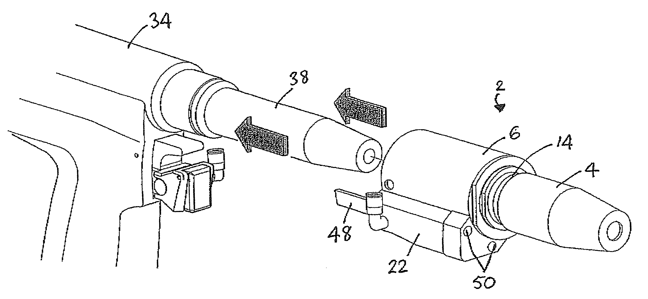
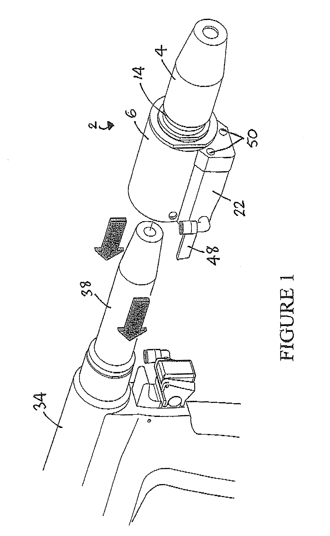
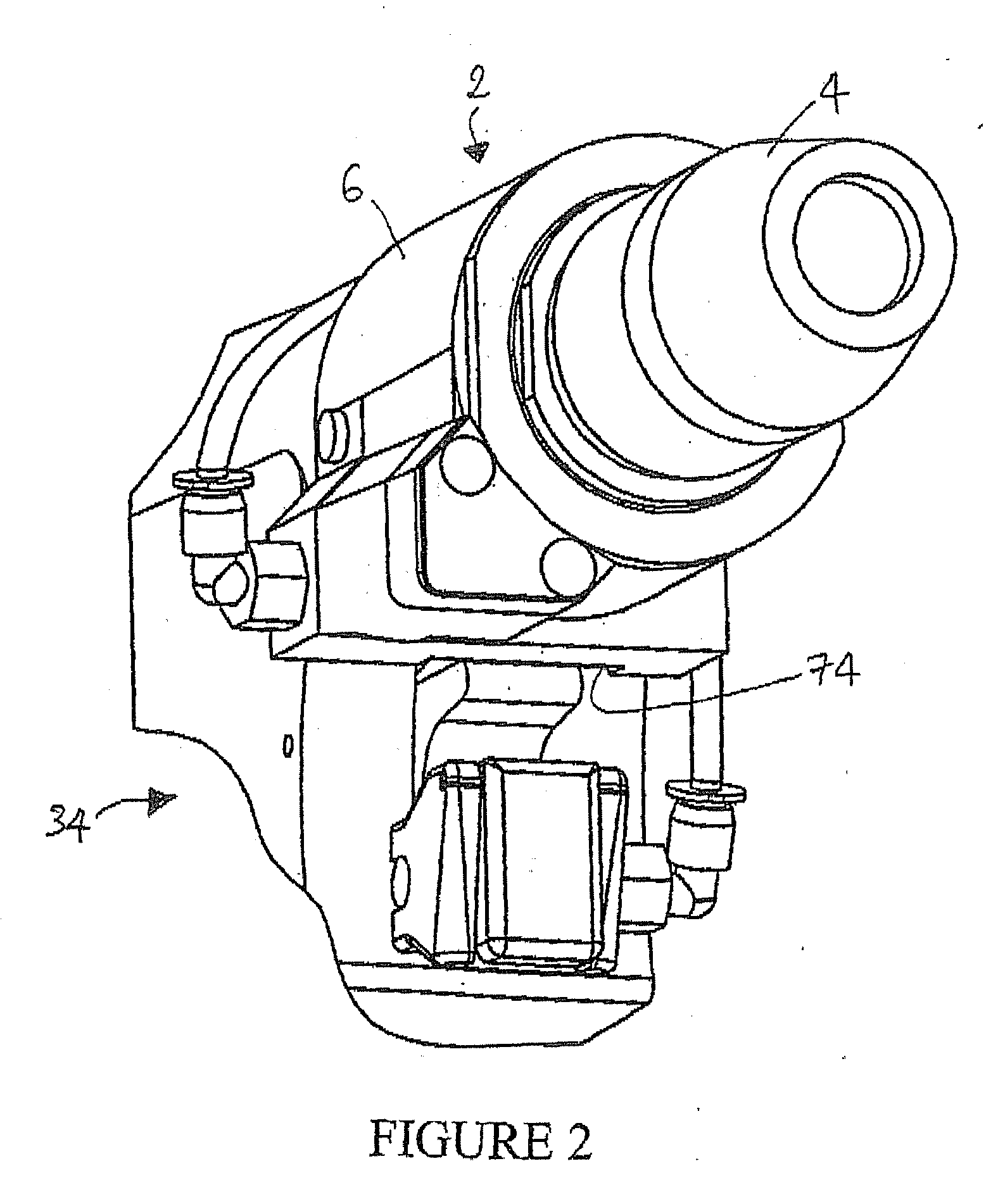
[0026]Referring to FIG. 1, the nose assembly 2 comprises a sleeve 4 and a housing 6. As shown in FIG. 5, the housing 6 houses a compression spring 8, and a collar 10. Collar 10 is provided with an internal thread (not shown), and is movable within the housing 6 against the compression of the spring 8. An external thread 14 (FIG. 1) provided on the sleeve 4 engages with the collar thread 12, and a first locknut 16 is provided on the sleeve thread 14 between the sleeve 4 and the housing 6. The threads 12, 14 and first locknut 16 allow a first level of adjustment of the assembly, by allowing the sleeve 4 to be threaded in to the collar 10 as far as necessary (according to the size of the head of the fastener which is to be installed) and subsequently locked in position by the first locknut 16.

[0027]Referring to FIG. 5, a plunger means 18 is attached to the sleeve 4 via an arm 20, such that movement of the sleeve 4 within the housing 6 causes corresponding movement of the plunger means ...


PUM

PropertyMeasurementUnit
Flow rateaaaaaaaaaa
Electrical resistanceaaaaaaaaaa

Abstract

A nose assembly for fitting onto a fastener installation tool for installing fasteners of the type in which a part of the fastener is broken off during the installation process, the nose being provided with a housing and a sleeve, the sleeve having a spring, and a collar which is movable within the housing against resistance of the spring, wherein plunger means are provided on the collar, and wherein the sleeve is threadably engaged with the collar, such that movement of the sleeve causes corresponding movement of the collar and plunger means, the plunger means being arranged to actuate a trigger thereby to open an air valve and allow a flow of compressed air through the tool, thereby to allow installation of the fastener into a workpiece.

Description

FIELD OF THE INVENTION[0001]This invention relates to a nose assembly for a fastener installation tool of the type wherein parts of fasteners are broken off during installation of the fastener.BACKGROUND OF THE INVENTION[0002]Fastener installation tools can utilise a supply of compressed air, which is supplied to the tool and subsequently routed through a central bore within the tool head piston in order to propel broken off fastener stems into a collecting bottle at the rear of the tool. Compressed air is also routed through a vacuum generator to create a vacuum to hold the fastener in place in the tool nosepiece prior to installation. When an external trigger is pressed, actuation means cause a head piston to be driven along a bore to cause a jaw-assembly to grip and pull a fastener stem which has been inserted into the tool nosepiece The trigger also causes an air valve to open and allow air to flow through the tool to propel the broken off stem into the bottle.[0003]Prior to ins...

Claims


Application Information

Patent Timeline
IPC IPC(8): B23P11/00
CPCB21J15/043B21J15/10B21J15/105Y10T29/49943Y10T29/5373Y10T29/53735Y10T29/53739B21J15/28
Inventor DEAR, AIDEN
Owner AVDEL UK LTD
Learn More