
High-emissivity infrared radiation coating layer material system used in high temperature environment (800 DEG C) and preparation method for high-emissivity infrared radiation coating layer material system

A technology of infrared radiation coating and high emissivity, which is applied in the direction of coating, metal material coating process, spray evaporation, etc., can solve the problems of unsatisfactory thermal shock resistance, low bonding strength, and unusability, and achieve production High efficiency, mature preparation process and easy preparation

Inactive Publication Date: 2019-11-29
NAT UNIV OF DEFENSE TECH
View PDF4 Cites 4 Cited by
  • Summary
  • Abstract
  • Description
  • Claims
  • Application Information

AI Technical Summary

Problems solved by technology

[0006] The technical problem to be solved by the present invention is to overcome the shortcomings that the existing infrared radiation coating system cannot be used at high temperature (800°C), and secondly, the bonding strength is not high, and the thermal shock resistance is not ideal enough, and a high-temperature high-emissivity coating system is provided. Infrared radiation coating material system (SiO 2 -Cr 2 o 3 -TiO 2 Coating system) and preparation method thereof, is a kind of coating material system that formula is simple, raw material is easy to obtain, and can be used under high temperature, widens the scope of application of infrared radiation coating system, is suitable for industrialized production

Method used


Image

  • High-emissivity infrared radiation coating layer material system used in high temperature environment (800 DEG C) and preparation method for high-emissivity infrared radiation coating layer material system
  • High-emissivity infrared radiation coating layer material system used in high temperature environment (800 DEG C) and preparation method for high-emissivity infrared radiation coating layer material system
  • High-emissivity infrared radiation coating layer material system used in high temperature environment (800 DEG C) and preparation method for high-emissivity infrared radiation coating layer material system

Examples


Embodiment 1

[0030] A high-temperature high-emissivity infrared radiation coating material system, wherein SiO 2 45% (mass ratio), Cr 2 o 3 40%, TiO 2 15%.

[0031] The preparation method comprises the following steps:

[0032] (1) take three kinds of material powders according to mass ratio;

[0033] (2) Carry out low-energy ball milling in a horizontal ball mill, using a polyurethane ball mill tank, zirconia grinding balls (ball-to-material ratio is 3:1), deionized water as a dispersion medium, and adding hydroxymethyl fiber equivalent to 1.0% of the raw material powder mass element, the ball milling time is 48h;

[0034] (3) Agglomerated powder was obtained by granulating by spray drying process, wherein the air inlet temperature was 200°C, the air outlet temperature was 80°C, the plunger pump speed was 1000r / min, and the atomization disk speed was 16000r / min;

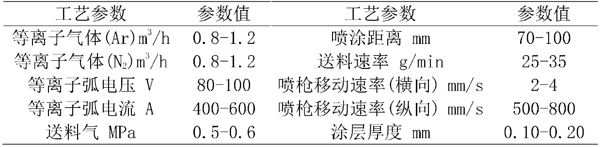
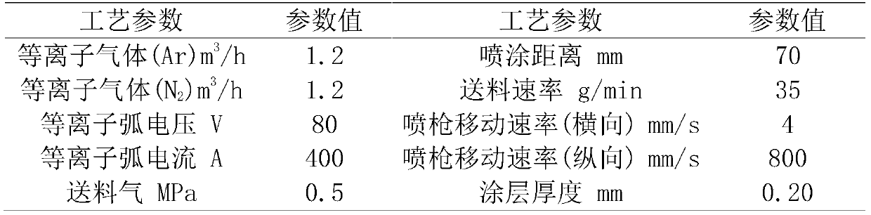
[0035] (4) Calcining the agglomerated powder at high temperature to obtain a finished powder suitable for the plasma ...

Embodiment 2

[0043] A high-temperature high-emissivity infrared radiation coating material system, wherein SiO 2 50% (mass ratio), Cr 2 o 3 40%, TiO 2 10%.

[0044] The preparation method comprises the following steps:

[0045] (1) take three kinds of material powders according to mass ratio;

[0046] (2) Carry out low-energy ball milling in a horizontal ball mill, using a polyurethane ball mill tank, zirconia grinding balls (ball-to-material ratio is 3:1), deionized water as a dispersion medium, and adding hydroxymethyl fiber equivalent to 2.0% of the raw material powder mass element, the ball milling time is 60h;

[0047] (3) Agglomerated powder was obtained by granulating by spray drying process, wherein the temperature of the air inlet was 180°C, the temperature of the air outlet was 50°C, the speed of the plunger pump was 800r / min, and the speed of the atomizing disc was 20000r / min;

[0048] (4) Calcining the agglomerated powder at high temperature to obtain a finished powder...

Embodiment 3

[0055] A high-temperature high-emissivity infrared radiation coating material system, wherein SiO 2 55% (mass ratio), Cr 2 o 3 40%, TiO 2 5%.

[0056] The preparation method comprises the following steps:

[0057] (1) take three kinds of material powders according to mass ratio;

[0058] (2) Carry out low-energy ball milling in a horizontal ball mill, using a polyurethane ball mill tank, zirconia grinding balls (ball-to-material ratio is 3:1), deionized water as a dispersion medium, and adding hydroxymethyl fiber equivalent to 1.5% of the raw material powder mass element, the ball milling time is 72h;

[0059] (3) Agglomerated powder was obtained by granulating by spray drying process, wherein the temperature of the air inlet was 150°C, the temperature of the air outlet was 30°C, the speed of the plunger pump was 500r / min, and the speed of the atomizing disc was 22000r / min;

[0060] (4) Calcining the agglomerated powder at high temperature to obtain a finished powder ...


PUM

PropertyMeasurementUnit
thicknessaaaaaaaaaa
thicknessaaaaaaaaaa

Abstract

The invention discloses a preparation method for a high-emissivity infrared radiation coating layer material system used in a high temperature environment (800 DEG C) and belongs to the field of inorganic materials. The preparation method comprises the following steps of by taking silicon oxide as a base material, chromium oxide as a main radiation agent and titanium oxide as a high-radiation additive, fully and uniformly mixing raw materials through a low-energy ball milling and mixing process, preparing a finished powder product suitable for a plasma spraying process with a spray drying granulation process, and finally, performing a plasma spraying process on a composite panel to prepare a high-emissivity infrared radiation coating layer. The SiO2 / Cr2O3 / TiO2 coating layer system has relatively high emissivity, high thermal shock resistance and infrared radiation performance, is mature in adopted preparation process, high in production efficiency, wide in raw material source, liable to prepare, simple to operate and is hopeful in and mass production in the industrial field and has a wide application prospect.

Description

technical field [0001] The invention belongs to the technical field of inorganic materials, and relates to the preparation of a high-temperature and high-emissivity infrared radiation coating material system by a plasma spraying method, in particular to a high-temperature and high-emissivity infrared radiation coating material system and a preparation method thereof. Background technique [0002] When a space vehicle flies in the atmosphere at a high Mach number, serious aerodynamic heating will occur on the surface of the vehicle. With the rapid development of aerospace technology, aerospace vehicles have more stringent requirements for thermal protection structures, requiring thermal protection structures to have a series of comprehensive characteristics such as curved surface shape, high toughness, high strength, large size, low thermal conductivity, and low density. . The infrared radiation rate of the surface of thermal protection materials is generally low. If the inf...

Claims


Application Information

Patent Timeline
Patent Type & Authority Applications(China)
IPC IPC(8): C23C4/134C23C4/10B02C17/10B02C17/18B02C17/20B01D1/18B01J2/04
CPCB01D1/18B01J2/04B02C17/10B02C17/18B02C17/20C23C4/10C23C4/134
Inventor 向阳曹峰刘荣军彭志航
Owner NAT UNIV OF DEFENSE TECH
Learn More