
Heat exchanger used for high-pressure freezing type compressed air dryer

A compressed air and refrigerated technology, which is applied in refrigerators, dry solid materials, evaporators/condensers, etc., can solve the problems of difficult processing, difficult to guarantee safety, and long cycle, so as to reduce processing cycle and cost, Easy to purchase, make and assemble

Pending Publication Date: 2019-11-26
上海阿普达实业有限公司
View PDF0 Cites 0 Cited by
  • Summary
  • Abstract
  • Description
  • Claims
  • Application Information

AI Technical Summary

Problems solved by technology

In low-pressure refrigerated dryers with a pressure less than 1.2MPa, the combined heat exchangers mostly use shell-and-tube heat exchangers, plate-fin heat exchangers, and plate heat exchangers; In the refrigerated dryer, shell and tube heat exchangers are mostly used, and some small refrigerated dryers also use casing heat exchangers, but the effect is not very satisfactory; There are no mature products for air dryers at present. The main reason is that the traditional shell-and-tube high-pressure combined heat exchanger has complex structural design, difficult processing, long cycle time, high material cost and supervisory inspection cost, and safety is difficult to guarantee.
The high-pressure refrigerated compressed air dryer made by traditional welding and expansion joints is prone to the risk of compressed air or refrigerant leakage due to minor process defects, and the welding process is prone to adverse effects on material strength and stress.

Method used


Image

  • Heat exchanger used for high-pressure freezing type compressed air dryer
  • Heat exchanger used for high-pressure freezing type compressed air dryer

Examples


Embodiment Construction

[0050] The present invention will be described in detail below in conjunction with the accompanying drawings and specific embodiments. The present invention is not limited to this embodiment, and other embodiments may also belong to the scope of the present invention as long as they conform to the gist of the present invention.

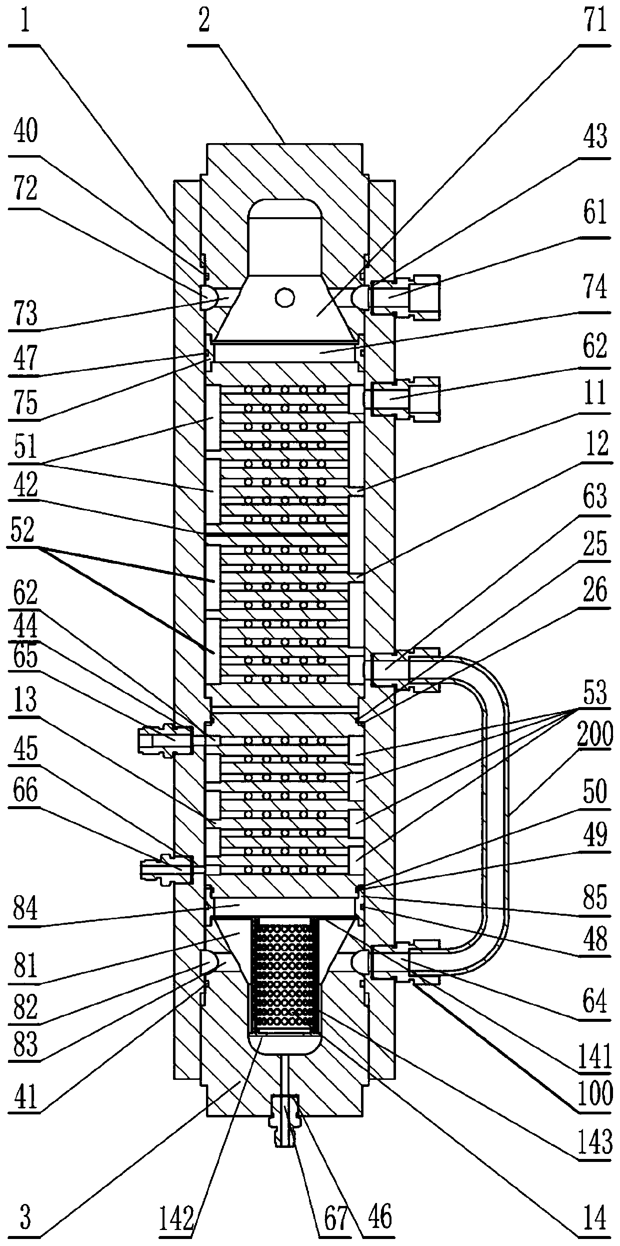
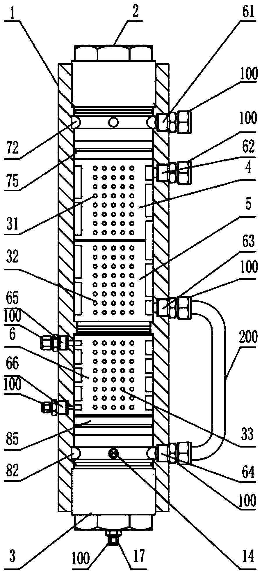
[0051] In a preferred embodiment of the present invention, based on the above-mentioned problems existing in the prior art, a heat exchanger for a high-pressure refrigerated compressed air dryer is now provided, such as figure 1 with figure 2 shown, including:

[0052] Cylindrical housing 1, the top of cylindrical housing 1 is provided with an upper cover 2 that is threadedly connected with cylindrical housing 1, and the bottom end of cylindrical housing 1 is provided with cylindrical housing The lower cover 3 of the body 1 threaded connection;

[0053] A first O-ring 40 is radially sealed between the upper cover 2 and the inner wall of the cylind...


PUM


Abstract

The invention provides a heat exchanger used for a high-pressure freezing type compressed air dryer, and relates to the technical field of compressed air aftertreatment. The heat exchanger comprises acylindrical shell, a first refrigerant through hole, a second d refrigerant through hole and a condensation water drainage through hole. An upper sealing cover and a lower sealing cover are arrangedat the two ends of the cylindrical shell. At least one first precooling reheater core, at least one second precooling reheater core, an evaporator core and a gas-water separator core are arranged between the upper sealing cover and the lower sealing cover from top to bottom. A first compressed air through hole, a second compressed air through hole, a third compressed air through hole and a fourthcompressed air through hole are formed in one side wall of the cylindrical shell from top to bottom. The fourth compressed air through hole communicates with the third compressed air through hole through a communicating pipe. The first refrigerant through hole is formed in the side wall of the cylindrical shell. The second refrigerant through hole is arranged below the first refrigerant through hole. The condensation water drainage through hole is formed in the bottom of the lower sealing cover. The heat exchanger is safe, reliable, extremely convenient to assemble, simple in structure and convenient to purchase and manufacture, and the machining period and cost are reduced.

Description

technical field [0001] The invention relates to the technical field of post-processing equipment for compressed air, in particular to a heat exchanger for a high-pressure refrigerated compressed air dryer. Background technique [0002] In modern industrial production, compressed air is an important energy source. Compressed air is mainly obtained by compressing air through an air compressor. In the air source system, the air directly discharged from the air compressor contains many impurities, mainly composed of water. If it is used directly without treatment, the impurities in the air will cause great harm to the components in the system, increase the maintenance cost of the equipment, shorten the service life, and pollute the product in severe cases. scrapped. At the same time, the compressed air contains water with a relative humidity of 100%. As it cools in the pipeline, the water will precipitate out. In the compressed air system, if there is water, it will increase th...

Claims


Application Information

Patent Timeline
IPC IPC(8): F25B39/00F26B5/06B01D53/26
CPCF25B39/00F26B5/06B01D53/265
Inventor 陈荣耀张剑敏
Owner 上海阿普达实业有限公司
Learn More