An online manageable air-cooled screw chiller and management system
An air-cooled screw and chiller technology, which is applied to irreversible cycle compressors, refrigerators, compressors, etc., can solve the problems affecting work efficiency and work progress, high refrigeration power, and low heat exchange efficiency between evaporators and condensers. and other problems to achieve the effect of reducing maintenance time, improving heat exchange efficiency, and improving refrigeration quality
- Summary
- Abstract
- Description
- Claims
- Application Information
AI Technical Summary
Problems solved by technology
Method used
Image
Examples
Embodiment 1
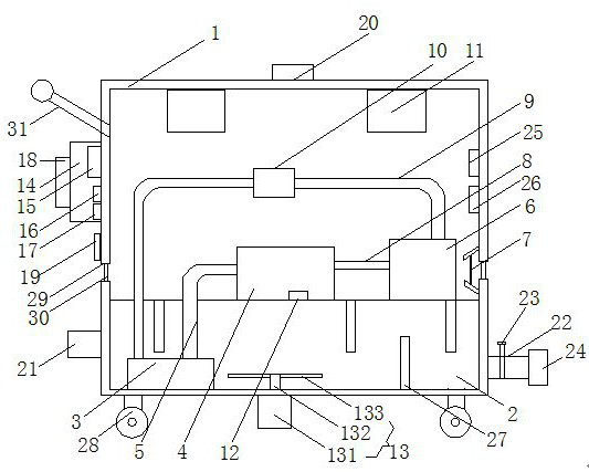
[0024] Embodiment 1: An air-cooled screw chiller that can be managed online, including a box body 1, which provides support and placement space. The bottom of the box body 1 is provided with a cooling box 2, which provides moisture storage and ensures moisture cooling. An evaporator 3 is provided on the left side of the bottom of the cooling box 2 to realize heat-absorbing refrigeration in contact with moisture. A screw compressor 4 is provided on the left side of the upper end of the cooling box 2. After the refrigerant is adiabatically compressed by the screw compressor 4, In the state of high temperature and high pressure, the air inlet of the screw compressor 4 is provided with a first conveying pipe 5 to transport the refrigerant. The air port is connected, and the upper right side of the cooling box 2 is provided with a condenser 6, and the inside of the condenser 6 is provided with a pressure sensor 12, and the air inlet of the condenser 6 is connected with the air outle...
Embodiment 2
[0026] The difference between this embodiment and Embodiment 1 is:
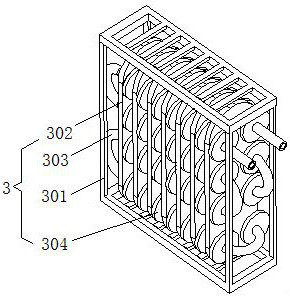
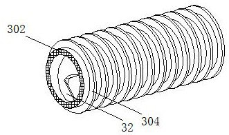
[0027] In this embodiment, the evaporator 3 includes an installation frame 301 fixedly connected to the bottom surface on the left side inside the cooling box 2, and the inside of the installation frame 301 is provided with evenly distributed heat conduction plates 302, and heat exchange tubes 303 are interspersed in the tube holes of the heat conduction plates 302 , the inner wall of the heat exchange tube 303 is provided with a spiral piece 32, the spiral piece 32 coincides with the central axis of the heat exchange tube 303, the heat exchange tube 303 is a serpentine heat exchange tube, and the surface of the heat exchange tube 303 is provided with evenly distributed circles Shaped heat conduction sheet 304, the circular heat conduction sheet 304 is located between two adjacent heat conduction plates 302, the condenser 6 includes a placement frame 61 fixedly connected to the upper right side of the cooling ...
Embodiment 3
[0030] The difference between this embodiment and Embodiment 1 is:
[0031] In this embodiment, the heat dissipation structure 11 includes a built-in tube 111 arranged inside the installation hole, a mounting frame 112 is provided on the inner wall of the built-in tube 111, and an axial flow fan 113 is provided at the bottom of the mounting frame 112, and the rapid cooling structure 13 includes and The bottom end of the cooling box 2 is rotatably connected to the rotating shaft 132 by a bearing. The upper end of the rotating shaft 132 extends to the inside of the cooling box 2 and a stirring rod 133 is arranged at an equal angle at the end. The bottom surface of the box body 1 is provided with a servo motor 131. The output shaft of the servo motor 131 runs through the bottom wall of the cooling box 2 and is fixedly connected to the bottom end of the rotating shaft 132 . The input ends of the axial flow fan 113 and the servo motor 131 are electrically connected to the output end...
PUM
 Abstract
Description
Claims
Application Information
 - R&D
- Intellectual Property
- Life Sciences
- Materials
- Tech Scout
- Unparalleled Data Quality
- Higher Quality Content
- 60% Fewer Hallucinations
Browse by: Latest US Patents, China's latest patents, Technical Efficacy Thesaurus, Application Domain, Technology Topic, Popular Technical Reports.
© 2025 PatSnap. All rights reserved.Legal|Privacy policy|Modern Slavery Act Transparency Statement|Sitemap|About US| Contact US: help@patsnap.com


