Wind-solar complementary and piezoelectric technology integrated road speed reduction device and construction method thereof
A technology of wind-solar hybrid and deceleration device, which is applied in circuit devices, battery circuit devices, roads, etc., can solve the problem that road deceleration devices are blank, and achieve the effects of improving land use efficiency, extending service life, and ensuring driving safety
- Summary
- Abstract
- Description
- Claims
- Application Information
AI Technical Summary
Problems solved by technology
Method used
Image

Examples
Embodiment 1
[0044] A wind-solar hybrid and piezoelectric technology-integrated road deceleration device, including a pavement basic module, a photovoltaic power generation module, a wind power generation module, a piezoelectric module, a power storage module, a power control device, and a power load;
[0045] The photovoltaic power generation module includes photovoltaic modules, photovoltaic module clamps and brackets required to connect photovoltaic modules. Photovoltaic modules should be arranged with the best inclination angle, or they can be tiled according to the actual situation. Photovoltaic power generation modules can be mainly used in the sky above the road. Depending on the orientation of the road, they can also be selected to be applied on both sides of the bracket above the road speed bump. The output end of the photovoltaic power generation module is connected with the energy storage module.
[0046] The wind power generation module includes wind power generation components,...
Embodiment 2
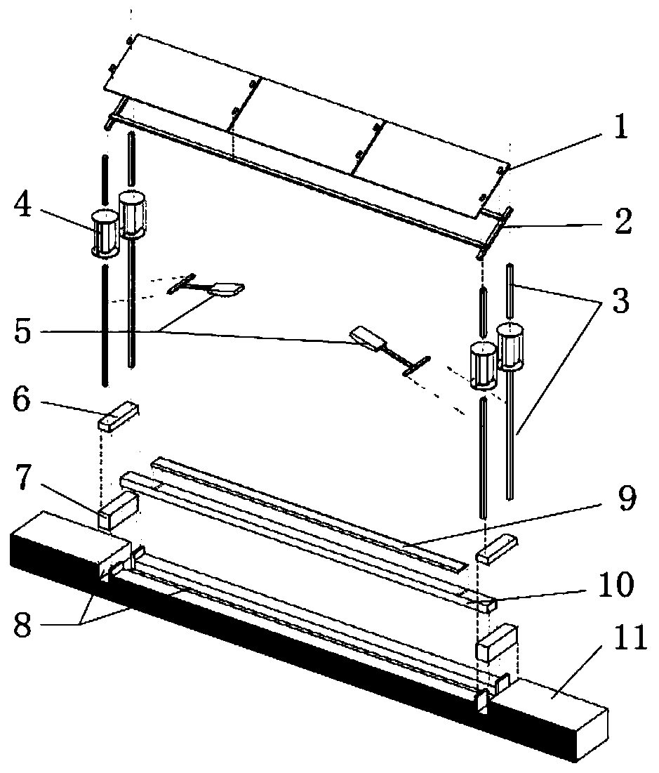
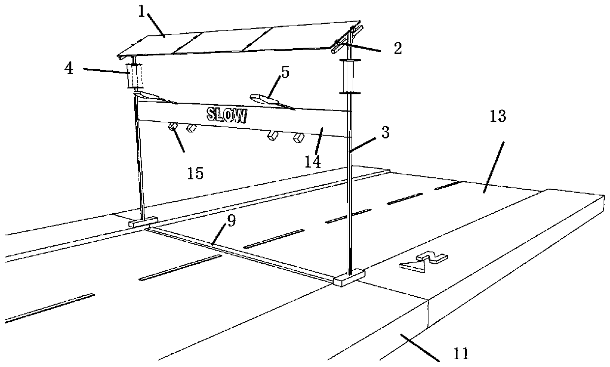
[0052] like figure 1 As shown, in the actual application process of this patent, the road surface is slotted, the piezoelectric crystal and the piezoelectric transmission device are installed in the road slot, and the electric energy control device and the energy storage module in the slot on both sides of the road are connected. The brackets for fixing photovoltaic power generation modules and wind power generation modules are arranged on both sides of the road, and the top is connected to the photovoltaic module brackets. Single-axis photovoltaic module brackets can be selected according to actual conditions (such as figure 2 and image 3 The top PV modules shown are single-axis brackets). A lightning rod needs to be installed on the top of the bracket. Wind generators can be arranged on the supports on both sides of the road. The inside of the bracket is a cavity. The wires of the photovoltaic module and the wind power generation module can be placed in the cavity, and ...
Embodiment 3
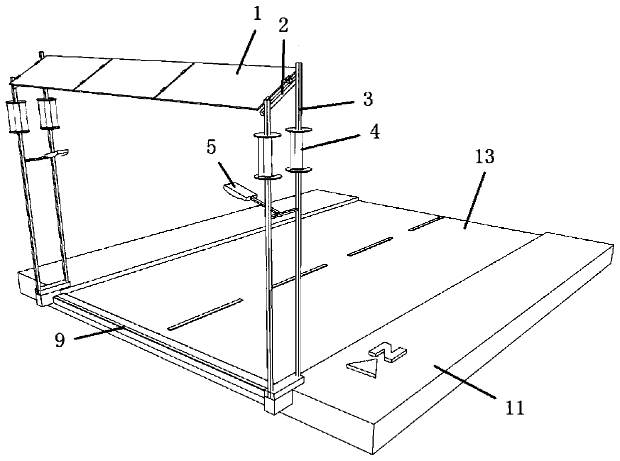
[0055] like figure 2 Shown is one application when the road is oriented north-south. In this way, the photovoltaic module adopts the traditional fixing method, using four brackets for fixing, and the photovoltaic module can be set to the optimal inclination angle. Vertical axis wind power generation components are used, and road speed bumps are connected with piezoelectric crystals. The electric energy control device controls the electric energy generated by the photovoltaic power generation module, the wind power generation module and the piezoelectric module, and inputs it to the energy storage module, and the surplus power is connected to the grid. The energy storage module supplies power to the street lights, which illuminate the road at night.
PUM
 Abstract
Description
Claims
Application Information
 - R&D
- Intellectual Property
- Life Sciences
- Materials
- Tech Scout
- Unparalleled Data Quality
- Higher Quality Content
- 60% Fewer Hallucinations
Browse by: Latest US Patents, China's latest patents, Technical Efficacy Thesaurus, Application Domain, Technology Topic, Popular Technical Reports.
© 2025 PatSnap. All rights reserved.Legal|Privacy policy|Modern Slavery Act Transparency Statement|Sitemap|About US| Contact US: help@patsnap.com